Question about a five pin ignition module
 08-06-2011, 08:20 PM
#1
New Member
Thread Starter
Join Date: Aug 2011
Posts: 6
Likes: 0
Received 0 Likes
on
0 Posts
Question about a five pin ignition module
How long can the 'twisted pair' be between the pick up in the distributor and the five pin ignition module?
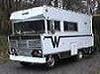
I am working on a 1972 motorhome and want to move the module inside under the dash. It would require the signal wires to be lengthened about 5-6 feet. I'm working on a 318.
I am working on a 1972 motorhome and want to move the module inside under the dash. It would require the signal wires to be lengthened about 5-6 feet. I'm working on a 318.
 08-07-2011, 08:02 AM
#2

I would NOT do that. The pigtail on some of the /6's is fairly long, but the thing is, lately, there seems to be a few people having trouble with these. The issues I've assumed are:
Some cars with harness/ bulkhead connector problems don't supply enough ignition voltage for reliable starting (voltage to the ECU)
Some distributors don't trigger reliably, a combination of worn shaft, wrong reluctor gap, and POSSIBLY reduced magnetism in the pickup
ADDITIONALLY anytime you have a SIGNAL LINE such as this pickup, which is a fairly low current, low voltage line, it is subject to NOISE PICKUP due to other circuits in the car.
WHY do you think you need to move it?
08-07-2011, 01:56 PM
#3
New Member
Thread Starter
Join Date: Aug 2011
Posts: 6
Likes: 0
Received 0 Likes
on
0 Posts
I would NOT do that. The pigtail on some of the /6's is fairly long, but the thing is, lately, there seems to be a few people having trouble with these. The issues I've assumed are:
Some cars with harness/ bulkhead connector problems don't supply enough ignition voltage for reliable starting (voltage to the ECU)
Some distributors don't trigger reliably, a combination of worn shaft, wrong reluctor gap, and POSSIBLY reduced magnetism in the pickup
ADDITIONALLY anytime you have a SIGNAL LINE such as this pickup, which is a fairly low current, low voltage line, it is subject to NOISE PICKUP due to other circuits in the car.
WHY do you think you need to move it?
Some cars with harness/ bulkhead connector problems don't supply enough ignition voltage for reliable starting (voltage to the ECU)
Some distributors don't trigger reliably, a combination of worn shaft, wrong reluctor gap, and POSSIBLY reduced magnetism in the pickup
ADDITIONALLY anytime you have a SIGNAL LINE such as this pickup, which is a fairly low current, low voltage line, it is subject to NOISE PICKUP due to other circuits in the car.
WHY do you think you need to move it?
And another question
What should I be seeing from the pick up signal wires when cranking the engine over? I was seeing around 300mv AC
And what is the Ohms reading for the pickup?
Thanks for the help.
08-07-2011, 08:32 PM
#4
The pickup should "generate" about 1v AC on a meter when cranking.
If you really have a 4 volt drop that is WAY too much. Here's how to double check: Put one probe of your meter on coil+ and the other on battery positive. This will measure the drop directly. On the motorhome, does this use a bulkhead connector? IF it does, this is the first place I'd check for drop
If the engine ran OK with a two-pin ballast, there is NO need to go to a 4 pin, unless you want to insure that you can use a 5 pin ECU. Here's the deal on them:
You can NOT tell a 4 pin ECU from a 5 necessarily by looking, because some 4 pin boxes have 5 pins. You'll have to "ohm out" the 5th pin to find out if it's connected to anything in the box.
A 4 terminal ECU will work with EITHER a 2 or 4 terminal resistor
A 5 terminal ECU MUST use a 4 terminal resistor.
Here's how traditional Mopar igniton switches work:
You have the separate accessory feed output
You have the traditional "ignition run" or IGN1 usually dark blue, hot only when key is in "run"
You have trational yellow "start" wire which operates the starter relay when cranking, if the neutral switch is grounded
You have traditional brown "ignition bypass" also called "ign2" which goes to the coil+ side of the ignition resistor. Hot ONLY when cranking with the key
08-08-2011, 09:24 AM
#5
New Member
Thread Starter
Join Date: Aug 2011
Posts: 6
Likes: 0
Received 0 Likes
on
0 Posts
I verified the voltage drop by measuring directly behind the ignition switch. There is no bulkhead connector. The ignition module is within sight of the ignition switch and has a straight wire going to it.
I do recall measuring the pick up coil while cranking at the end of my extension and at the distributor itself. The readings seemed to be the same.
The chassis electrical seems to be mostly mopar production vs a motorhome rats nest. It does have the main ignition circuit plus the second ignition circuit that is hot while cranking for the coil. There is a classic Winnebago forum that has lots of info and was able to get a wiring diagram for this chassis.
Is there an ohms value to test the pick up coil?
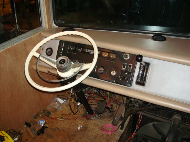
It's still in progress so the wires are not tied up yet but this is the recoverd dash.
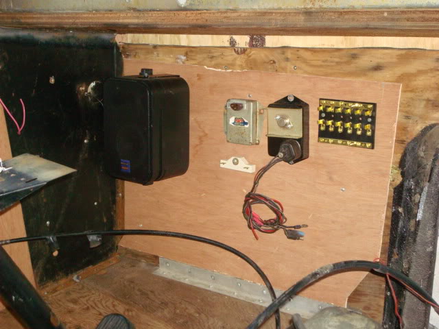
Here is what the module looks like under the dash. This pic was taken while the dash was still out.
I do recall measuring the pick up coil while cranking at the end of my extension and at the distributor itself. The readings seemed to be the same.
The chassis electrical seems to be mostly mopar production vs a motorhome rats nest. It does have the main ignition circuit plus the second ignition circuit that is hot while cranking for the coil. There is a classic Winnebago forum that has lots of info and was able to get a wiring diagram for this chassis.
Is there an ohms value to test the pick up coil?
It's still in progress so the wires are not tied up yet but this is the recoverd dash.
Here is what the module looks like under the dash. This pic was taken while the dash was still out.
Last edited by tmackx; 08-08-2011 at 09:33 AM.
08-08-2011, 02:59 PM
#6
Not sure of the ohms reading for the pickup. Generally, if they show "something" and nothing to ground, that part of 'em is OK, but that doesn't mean they "work."
By the way, I'm not sure about the regulator/ module. but DO NOT mount that resistor on a wood surface. They get VERY hot in operation
By the way, I'm not sure about the regulator/ module. but DO NOT mount that resistor on a wood surface. They get VERY hot in operation
08-08-2011, 07:00 PM
#7
New Member
Thread Starter
Join Date: Aug 2011
Posts: 6
Likes: 0
Received 0 Likes
on
0 Posts
You can't see it in the pick but there is a spacer that is holding the resistor off the wood about a 1/4". I will keep an eye on the other two. Now that I look at it again it looks like a big heat sync on top of the ignition module.
08-23-2011, 08:47 AM
#8
New Member
Thread Starter
Join Date: Aug 2011
Posts: 6
Likes: 0
Received 0 Likes
on
0 Posts
I found my voltage drop. Apparently when the stock ignition switch goes to crank it shuts off power to ign 1 and powers ignition 2. I was reading the voltage coming back across the resistor to ign 1. I tried a jumper from straight battery to the 12 volt feed on the module with no luck. I solved my problem anyways. Bought the original distributor and dropped it in. Started up and ran like a champ. I don't like to give up but I had spent too much time and was ready to move on. This will be a low mileage toy so the points will do just fine. I paid the core and keeping the electronic distributor in case I ever want to revisit the electronic side again.
08-23-2011, 10:26 AM
#9
Some things you might keep in mind for "next time."
I'm not clear if this system was ever working? You seem to have said in your last post that you were converting from points to electronic?
MAKE SURE that the module you had was FOUR terminal --with a 2 pin resistor--read my other post -- A 5 pin box MUST use a 4 pin resistor
You can NOT tell a 4 terminal ECU from a 5, as "at least some" have 5 pins but the 5th pin is not connected
Next, folks seem to have a lot of trouble with these breakerless distributors. One tune-up guy indicated he replaces a fair amount of "seemingly good" pickup coils, and speculation was that some may be losing magnetism
You are correct that "ignition run" (ign1) goes dead during crank. This is only an issue if 1--you are starting the engine by jumpering the start relay, as you then have power through the resistor
2--if there is something wrong in the wiring/ switch
3--if the brown bypass circuit (ign2) did not get hooked up.
If you Google around, there are a fair number of people--including me--who have adapted a GM HEI module
These are VERY easy to hook up, just 4 connections, and no resistor needed
I first played with one of these on my Toyota powered Oliver/ Cletrac, and now run on on my Dart
Toy 20R powered Cletrac, 4 speed + 3 speed, governor off a D-2 Cat pony motor
08-23-2011, 02:23 PM
#10
New Member
Thread Starter
Join Date: Aug 2011
Posts: 6
Likes: 0
Received 0 Likes
on
0 Posts
It did work, and worked well. The pivot point was removing the dashboard and cleaning up the wiring around the engine. I found one of the pick up coil wires were twisted together with electrical tape and wondered how it even worked. There were other wires connected that way and a couple worn out solder splices in the charging circuit so I decided to dissasemble and reassemble with better connections. I had to have undone some trick the previous owner did to get it to work.
For those who may be interested
http://s561.photobucket.com/albums/s...ebago%20Brave/
For those who may be interested
http://s561.photobucket.com/albums/s...ebago%20Brave/

Thread
Thread Starter
Forum
Replies
Last Post
stazja01
General Technical Questions
20
08-23-2011 04:39 PM
76NY440_nTX
Do-It-yourself Section
3
06-12-2011 04:27 AM
GMdude
Do-It-yourself Section
5
07-09-2009 04:42 PM


