Wiring basics.
 01-02-2012, 12:09 AM
#1

Wiring basics.
Hello everybody, I have a 68 dodge coronet that has most of the mechanical problems taken care of, or in the process of getting them taken care of.
As for my electrical set up, the car no longer has power steering, or AC, so the pulley set up is sloppy. Is there a mounting bracket you all recommend for running the bare minimum of just the alternator?
Also, I'm using the old Harmonic balancer from the motor I rebuilt, its just about the only part i didnt buy new. Should I? Is it really worth it?
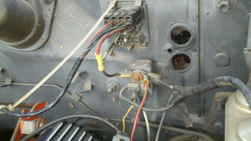
As for electrical, Ive got a set of MSD goodies Im gonna throw under the hood. I am trying to attach a pic of a part, and I want to know what its called. . . Lil Help ?
Its the part on the bottom with all the important wiring coming in or out of it. Can I get an idea of how it works, or what it is thats going on here?
btw my car is a 68 dodge coronet 500 I'm trying to resurrect.
Thanks for any help, love these forums, I could read this stuff all day!
- Fred.
As for my electrical set up, the car no longer has power steering, or AC, so the pulley set up is sloppy. Is there a mounting bracket you all recommend for running the bare minimum of just the alternator?
Also, I'm using the old Harmonic balancer from the motor I rebuilt, its just about the only part i didnt buy new. Should I? Is it really worth it?
As for electrical, Ive got a set of MSD goodies Im gonna throw under the hood. I am trying to attach a pic of a part, and I want to know what its called. . . Lil Help ?
Its the part on the bottom with all the important wiring coming in or out of it. Can I get an idea of how it works, or what it is thats going on here?
btw my car is a 68 dodge coronet 500 I'm trying to resurrect.
Thanks for any help, love these forums, I could read this stuff all day!
- Fred.
 01-02-2012, 12:12 AM
#2
umm
ok I figured out its the starter relay. Damn. So i think I know whats up, I really want to get this baby running, any tips?
Looking for bare minimum wiring setup just to see if she runs, get the brakes sorted out, test drives, etc.
Looking for bare minimum wiring setup just to see if she runs, get the brakes sorted out, test drives, etc.
01-02-2012, 12:43 PM
#4

You can download useable wiring diagrams over at "My mopar" along with some other goodies, here:
http://www.mymopar.com/index.php?pid=31
These two diagrams
http://www.mymopar.com/downloads/1968/68CoronetA.JPG
http://www.mymopar.com/downloads/1968/68CoronetB.JPG
There's other good stuff on that site, so browse around
Here's a thread at FABO with several full service manuals posted:
http://www.forabodiesonly.com/mopar/...al%2C+download
Here's a 69, but I dont remember if it's a complete manual or just the body manual
http://www.abodyjoe.com/pictures/Mis...e%20manual.pdf
Yes, the MAD article points up the problems with Mopar bulkhead connectors
So far as the starter relay, here's how Mopar ignition/ start systems worked for years and years
The start relay on older stick cars had the coil grounded, so had only 3 terminals
The start relay on ALL automatic cars had an extra "push on" terminal for the relay coil, as did the newer stick cars which have a clutch safety switch
The big stud is one of the relay contacts, as well as a junction point
The big "square" terminal is the other contact, and goes to to energize the starter solenoid
In order for an auto or a stick car with a clutch safety switch to "crank" the extra "push on" connector on the relay MUST see a ground from the neutral safety switch or the clutch safety switch.
Here's how Mopar ignition switches work, which are in reality several switches in one container.
The power for the IGN switch comes in off the ammeter circuit (red) This is NOT fused except for the fuse link, and comes from the factory welded splice in the under-dash harness in the ammeter circuit
The IGN switch has the following SEPARATE switch circuits:
large black, hot in "run" or "accessory" feeds power to the switched buss in the fuse box for stuff like radio, heater, wipers
dark blue, hot only in "run" feeds part of the instrument cluster, out through the bulkhead to the regulator and ignition system (dark blue) On newer cars, this also feeds the alternator field, the choke heater if used, and I believe the distributor solenoid if used. This is sometimes called IGN 1
Now "start" is a little tricky
The yellow on your start relay comes from ONE PLACE, and is the IGN switch start contacts that wire comes directly from the switch, out the bulkhead and to the relay, and is hot ONLY in "start." If the neutral safety switch is in park or neutral, the relay should energize, and that will fire the starter solenoid.
But now you need a "hot spark" for start, and the battery voltage sags during cranking. So the "IGN2" or ignition bypass circuit is used. This is a separate switch, hot only in start, and is a brown wire goes directly from the switch, through the bulkhead, to the Coil + side of the ballast resistor. In effect, it feeds "hot" voltage direct to the coil + during cranking.
It is VERY important to go through that bulkhead connector and upgrade the connectors, or as I did, just run new wire through the connector.
Consider headlight relays, and even consider a relay to operate the ignition/ regulator.
You can check just how bad the voltage drop in the IGN1 (run) circuit by doing the following:
Turn the key to "run", engine OFF. Make sure the points are closed, if you still run them, by checking the voltage at the coil -- IF the voltage is high, close to "same as battery" the points are open. Bump the engine until the voltage goes very low. This helps to put a load on this circuit during your test. Don't leave the key on for more than a couple of minutes.
So now, put one probe of your meter on the battery positive post, and the other probe on either the regulator IGN terminal, or the key side of the ballast resistor.
You are measuring the voltage drop from the battery -- through the fuse link -- through the bulkhead connector -- through the ammeter circuit -- through the IGN switch connector -- through the switch -- back out the switch connector -- and back out the bulkhead connector on the dark blue -- to the regulator and ignition.
You want to see a VERY low voltage, the lower the better. If over .2V (two tenths of a volt) show concern, if approaching or over 1/2 volt, you need to find out where the drop is.
(My old Dart before rewiring had a ONE VOLT drop in this circuit.)
This low voltage makes the regulator think the battery is low and ADDS to the charging voltage by the amount of the drop.
So far as "minimum wiring" to test drive the car, though, if you have to, just simply "hot wire" it. The coil resistor should have a blue wire going to it. Confrim that with the key on, this is hot (disconnect the wire for that test.) Clip a test lead to the end with ONE wire, the other end to the starter relay "big stud." Crank and start the car by jumpering a screwdriver/ pliers across the two largest, exposed terminals on the start relay.
That should at least get the thing running for a short test hop, assuming the points, etc, rest of ignition are OK
Last edited by 440roadrunner; 01-02-2012 at 12:46 PM.
01-02-2012, 07:38 PM
#5
thanks!
awesome!!!
thanks for the awesome reply!
I'll post more pics soon, I spent the day under the car busting my knuckles on the suspension today. Changing all the tie rod ends as they looked pretty worn. Also need to install the flaming river steering column kit I bought, and basically wire it up.
I spent a lot of time yesterday learning about the wiring woes and history of the b body and other mopars, it was a fascinating read, but its time to put the *** to the iron, as they say.
I really, really appreciate the response, and I'll keep you guys in mind.
- Fred.
01-02-2012, 07:52 PM
#6
After reading a bit further. . . .
OK, so I'm downloading the manual, definitely appreciate that. .
As for the wiring, I'm very comfortable with the concept, but how do I get to all this wiring behind the ammeter, etc?
This car has all kinds of delicate trim on the dash and I dont want to start tearing it apart unless I'm sure I need to. You guys have been here before so I thought I'd start here.
What I'm thinking is to pull the wires through my bulkhead a little bit, I actually want to extend them from the firewall into the engine compartment a bit to give me room to work, make some solid connections, heat shrink everything and figure out how to get it all nice and weatherproof, put some dielectric grease in there. . . cool. . .
but how involved is it to get to the wiring? How do I get into the dash?
Everything under the dash looks amazingly complete to me, even as messy as the engine compartment wiring is. I like this, I just cant get in there to work.
Patiently awaiting your reply. . .
Fred.
01-02-2012, 11:52 PM
#7
It's been about 35? years since I pulled the dash out of a car similar to yours. I would think the shop manual download should help you. There may be a few more over in the tech pages of "MyMopar."
To seriously get to the under-dash wiring, you pretty much need to pull the glove box, the radio, the ash try and the instrument cluster.
Bear in mind that to do any testing that requires vehicle power, you must either hook up the ammeter to make the circuit, or else take a small bolt and hook the two ammeter wires together.
If it were me, I would ASSUME that at the very least, the bulkhead connector, the fuse box, the headlight switch, and probably the ignition switch have connection issues. Melted / damaged connectors and insulation, etc. All of these components carry considerable current.
I'd also want to consider CHECKING the "in harness" welded splice. Just the other day, over at A-bodies, we had a guy who found a bad splice. That makes approximately 6 bad ones I've been associated with in my life.
I can't tell you just where in the harness this is, but you can get some idea by following the black ammeter wire and the main hot feed to the ignition switch.
01-03-2012, 08:10 AM
#8
Gotcha
and thanks again.
I did spend last night reading the manual and there is a section on how to remove the instrument cluster, I think my problem was that I was looking for a way to remove the whole thing at once. I think if I can pull my cluster, I can see what I'm working with, and get to some serious wiring.
I'm gonna try to hook up the ammeter too, hopefully it works. . . I know I changed the ignition switch in this thing when i was a kid, I havent worked on this car in about 8 years. . .. so it should still be ok.
None of the stock gauges have ever worked except for the speedometer, so this will give me a chance to test those out too.
Very cool man, I can't believe the resources that are out there now, the internet and all this information is just ridiculous. No more standing in the parts shop writing down firing orders or drawing cylinder head bolt torque patterns.
Sheesh!
Ok, I'm back at work now after a long break, so I'll check back in when I can.
01-04-2012, 05:48 PM
#9
Mopar Lover

Join Date: Apr 2009
Location: Michigan: The First Line of Defense From The Canadians!
Posts: 1,892
Likes: 0
Received 4 Likes
on
4 Posts
Good on ya! BTW, The old splices look like ****. Please re-do them properly to save yourself grief. For underhood I recommend non-insulated terminals with heatshrink. there are Utube videos to show you this. Once again, thank you internet! Good luck buddy!
01-04-2012, 10:27 PM
#10
hhahahah yep, already picked up some non insulated crimp and solder material, and a bunch of heat shrink tube. think Im gonna just drill through all of them and connect everything but the Ammeter. See what works and what doesnt. I'm sure by then Ill be an expert at removing and installing that dash.
01-05-2012, 09:01 AM
#11
Depending on your skills, some of us have modified voltmeters to replace the factory dash ammeter. I found this trick online, cannot take credit, but I bought a Sunpro voltmeter, tore it down, replaced the face with my original ammeter face, and adjusted the calibration pot in the meter so that 14V was the center mark on the ammeter.
Also, the newer cars went to a "shunt type" ammeter, and you might google around, there's been some guys do that. I bought a junkyard Ford external shunt ammeter, but it was not very adaptable to mine. I do prefer ammeters to voltmeters. I'm an old guy.
Also, the newer cars went to a "shunt type" ammeter, and you might google around, there's been some guys do that. I bought a junkyard Ford external shunt ammeter, but it was not very adaptable to mine. I do prefer ammeters to voltmeters. I'm an old guy.
01-05-2012, 10:00 AM
#12
hahah that sounds incredibly sweet. . . . but I'm not that worried about it. There is TONS left to do on this car, so I need to get her running first. I'm gonna bypass for now and run a volt meter. I'm gonna run a bunch of guages at first but want to get it looking semi stock inside eventually. maybe later, or maybe not at all. But for now, I've got plenty of electrical to tackle.
as for the "Depends on your skills"
well, all I've ever wired were guitars. this looks about the same with fatter wires and fuses, and a hell of a lot more electricity running through them. So I'll take it easy on the super custom original looking dash guage fabrication for now hahah
thanks tho, you guys have been a world of help.

Thread
Thread Starter
Forum
Replies
Last Post


