Delco alternator - starting/charge problems
 04-07-2012, 09:30 AM
#1
Mopar Fan
Thread Starter

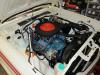
I have a 68 Dodge Coronet that came with a Delco alternator, pn 1101028, 80A. The car has started to exhibit poor starting and no charging. The starter has been rebuilt as has the alternator. The battery was moved to the trunk with a Taylor (1033) on/off switch. The cables for the battery are all 1/0 welding cable. I can only start the car with a second battery(booster) connected to the +ve stud(distribution block) in the engine compartment. When I check the battery in the trunk, I can see the voltage declining, NO charging.
When the Delco alternator was installed the voltage regulator was removed. The car was converted in 1992 and ran fine for many years until I moved the battery to the trunk. I am at a total loss as where the problem is and what it is. I do have the option to move the battery back to the engine compartment. I would like to leave it in the trunk.
Hoping that there is a solution out there.
 04-07-2012, 12:13 PM
#2

One google hit I found gives this as a 100A type 27SI.
Generally with Delco integral regulators, there are TWO general types:
The older "3 wire" hookup
The so called "one wire."
Trouble is OFTEN caused on the old "3 wire" types because of incorrect hookup. Originally, the no2 connection at the plug was "voltage sensing" and was hooked direct to a good battery source.
The no1 connection went through a resistor/ warning lamp combination and to the ignition switch. No1 was the "excitation" and warning lamp circuit
Many people make the MISTAKE of hooking no1 direct to switched 12V THIS WILL work "for awhile" but IT WILL eventually take out the diode trio and possibly the regulator. The reason is that on shutdown, the diode trio can "attempt" to become a charging source, and the tiny package was never designed for much current
SO
CHECK the brushes, are they free moving, worn out/ sticky in the brush holders?
CHECK or replace the diode trio. This is simply 3 diodes connected together at one end, so you put your ohmeter on "diode check" on the "long pigtail" and then read with the other probe on the other 3, one at a time. Then switch probe polarity. The diodes should all be "low" in one direction to the lone pigtail, and when reversed, should all 3 be "open."
If that does not show up anything, replace the regulator. It is up to you whether you get a "one wire" or "3 wire" regulator, but if you get a "3 wire" hook up the no1 connector with a diode in series to protect the trio
Notice in the diagram below that no2 is jumpered to the output stud, and no1 is wired with a diode in series, THE BAND OF WHICH is towards the alternator
I ran a Delco integral regulator setup way back in the early '70's on my 340, LONG before Al Gore invented the www.com
Which came from this website
http://www.ytmag.com/cgi-bin/viewit....talk&th=816120

ALSO, do you race? If you do, you need to pay attention to how your battery switch is set up. You cannot simply break the battery positive cable, because this will allow the charging system on a working engine to supply power to the engine, IE pulling the battery switch will not kill the engine. This will NOT pass NHRA tech. If the switch is simply for storage and parking, great.
Generally with Delco integral regulators, there are TWO general types:
The older "3 wire" hookup
The so called "one wire."
Trouble is OFTEN caused on the old "3 wire" types because of incorrect hookup. Originally, the no2 connection at the plug was "voltage sensing" and was hooked direct to a good battery source.
The no1 connection went through a resistor/ warning lamp combination and to the ignition switch. No1 was the "excitation" and warning lamp circuit
Many people make the MISTAKE of hooking no1 direct to switched 12V THIS WILL work "for awhile" but IT WILL eventually take out the diode trio and possibly the regulator. The reason is that on shutdown, the diode trio can "attempt" to become a charging source, and the tiny package was never designed for much current
SO
CHECK the brushes, are they free moving, worn out/ sticky in the brush holders?
CHECK or replace the diode trio. This is simply 3 diodes connected together at one end, so you put your ohmeter on "diode check" on the "long pigtail" and then read with the other probe on the other 3, one at a time. Then switch probe polarity. The diodes should all be "low" in one direction to the lone pigtail, and when reversed, should all 3 be "open."
If that does not show up anything, replace the regulator. It is up to you whether you get a "one wire" or "3 wire" regulator, but if you get a "3 wire" hook up the no1 connector with a diode in series to protect the trio
Notice in the diagram below that no2 is jumpered to the output stud, and no1 is wired with a diode in series, THE BAND OF WHICH is towards the alternator
I ran a Delco integral regulator setup way back in the early '70's on my 340, LONG before Al Gore invented the www.com
Which came from this website
http://www.ytmag.com/cgi-bin/viewit....talk&th=816120
ALSO, do you race? If you do, you need to pay attention to how your battery switch is set up. You cannot simply break the battery positive cable, because this will allow the charging system on a working engine to supply power to the engine, IE pulling the battery switch will not kill the engine. This will NOT pass NHRA tech. If the switch is simply for storage and parking, great.
Last edited by 440roadrunner; 04-07-2012 at 12:16 PM.
The following users liked this post:
moparcanblue (04-07-2012)
04-07-2012, 01:28 PM
#3
Mopar Fan
Thread Starter
Thanks for the reply and yes, it should be setup as per NHRA rules as we do race the car once in a while. Can you provide some wiring info on this?
Looking at your picture, the large #10 or 12 wire from the 2 wire connector goes to the starter relay labeled BAT. The other wire from the connector has been cut and taped. It does not go anywhere. I will go and check things. The rear on/off switch is a Taylor 4 prong unit.
Looking at your picture, the large #10 or 12 wire from the 2 wire connector goes to the starter relay labeled BAT. The other wire from the connector has been cut and taped. It does not go anywhere. I will go and check things. The rear on/off switch is a Taylor 4 prong unit.
04-07-2012, 05:35 PM
#4
OK, sounds like you have a "one wire" regulator, which is the only real difference between a "one wire" and "3 wire" Delco. I'd pull it apart, check the brushes, and if they look OK and the diode trio checks OK, replace the regulator. Probably would not hurt to replace brushes "just because." If you are unaware, there's a hole in the rear housing, you put the brushes "down" and stick a toothpick/ nail/ paper clip through the rear hole, and it holds the brushes
If you are using a 4 terminal disconnect, you are set up. How do you have it hooked up?
One way is to break the battery -- and you must break the hot, not the ground-- with the two large posts
Ground one of the small terminals, and run one no 14 wire up front from the remaining small terminal. Buy yourself a "continuous duty solenoid, and hook the no14 running up front to one of the small terminals of the solenoid.
Hook one of the large terminals to the stud on the starter relay, and fuse it according to the load you will have on it.
Break the "ignition run" wire out of the firewall
Hook the bulkhead side of the "run" wire to the remaining small terminal of the solenoid.
Hook your ignition loads, fuel pump, whatever else you want on the remaining large terminal
This way, you have a HUGE nice relay to handle switched "run" loads, and EITHER the key or the disconnect will break the loads. This will guarantee that the car dies when either the key or the disconnect is pulled.
04-08-2012, 01:16 AM
#5
Mopar Fan
Thread Starter
I was looking at the wiring at alternator. The original installation was a custom job so I am a lot confused.
The +ve battery cable is attached to one of the 1/2" bolts on the on/off switch with a jumper to a 3/16" bolt. The other 1/2" bolt feeds the distribution hub up front. There is a 125A fuse inline. The BAT terminal from the alternator feeds the other 3/16" bolt on the on/off switch, as per the Taylor diagram. The -ve cable runs from the battery directly to the engine block. From there a ground strap runs to the fire wall.
The voltage regulator and ignition ballast have been removed and jumpers added.
The #2 connector on the alternator is hooked up to a DKBL wire in the harness, why ?????. The #1 alternator wire is clipped and taped up.
I do not understand how the alternator is excited.
The starter is new and the alternator was just rebuilt. New brushes and voltage regulator. The car does/did run with alternator wiring. The voltage gauge would kickup when charging but not now.
When I try and start the car now, the start just clicks. If I add a jumper battery and connect it to the distribution hub where the +ve cable from the on/off switch is connected the started will click a few times then engage and the engine starts but there is no battery charging. We are just running off the batteries.
The batteries are AGM and are fully charged ( external charger ).
Just trying to get the car to start when I turn the key
We are looking at a complete rewire due to other problems but I would like to start with a working car.
Thanks for all of you input.
04-08-2012, 08:42 AM
#6
Super Moderator
The #2 connector on the alternator is hooked up to a DKBL wire in the harness, why ?????. That's the ignition curcuit and it's telling the alternator to turn on when you start the car. If it is a three wire with built in regulator you will need a another wire monitoring battery voltage for it to work. I run an 80 amp Nippon Denso alternator and it is hooked up just that way.
The following users liked this post:
moparcanblue (04-08-2012)
04-08-2012, 10:32 AM
#7
What you describe is a VERY poor setup.
FIRST, the small terminals of your disconnect were NEVER intended to handle heavy charging current
Here is an example of a Cole - Hearse double pole (4 terminal) switch. The small contacts ARE ONLY RATED at 20 amps!!
http://www.colehersee.com/home/item/cat/209/75903/
SECOND, by breaking the output of the alternator with the switch, EVERY time you do that you are disconnecting a heavy charging circuit, which does two things---it will cause a big arc that will eventually damage the small contacts in the switch, AND you cause a huge voltage spike that could damage the alternator regulator or diode trio
NORMALLY, the no2 wire is NOT switched, but rather fed directly to battery, just like in the diagram I posted, AND the no1 wire is in fact the excitation, but is MUST be treated as I mentioned
THE FACT that it worked this long with only no2 hooked up suggests that this may have a "one wire" regulator in it, and either no2 is a sensing lead (just like 3 wire) OR that the no2 / blue connection is superfluous.
I assume that the car battery is simply going dead. I'd charge it up and see where you stand If it seems to start / run OK after you get the battery charged, then you can chase the alternator.
The very first thing I'd do is check with a voltmeter on both of the small terminals of the disconnect, and compare that voltage with the voltage up front on the alternator output stud
Do this with the engine running at a good fast idle
IF the voltage is "way high" at some point, you have a break in the charging line/ bad disconnect
If the voltage is low everywhere, the alternator has failed.
Last edited by 440roadrunner; 04-08-2012 at 10:35 AM.
04-08-2012, 04:47 PM
#8
Mopar Fan
Thread Starter
I cannot talk to the alternator setup -- I do not know enough about it. I have attached the Taylor installation sheet. If you can clarify what they mean by alternator output, I would appreciate it.
I will make the changes suggested and see what happens.
I will make the changes suggested and see what happens.
04-08-2012, 04:58 PM
#9
One a typical Delco, "3 wire" with integral regulator, The big insulated stud --just like on a Mopar -- is the output
04-08-2012, 05:04 PM
#10
I certainly would, however, measure voltages as I suggested earlier, as the switch could have failed or some other wiring break could have broken the alternator charging path (output) on it's way to the battery.
It would be interesting to know if Taylor switches are "that much better" or whether they are just "playing the odds."
04-16-2012, 05:27 AM
#11
Mopar Fan
Thread Starter
Still working on this. We have decided to rewire the entire car and will include your suggestions in the rewire. This will take some time to accomplish on an 'as time is available' basis.
As I understand things, the alternator output wire is wired into the disconnect switch to "kill" the alternator generated power in case of an accident. In the "on" position the battery is charged.
I will do an additional test of removing the switch from the circuit and see if it starts better. It may need replacing again .
.
BTW: I did replace the disconnect switch last year as starting was intermittent. A new switch fixed that problem. I cut open the old switch the other day to see what it looked like inside. I found a lot of carbon buildup on one of the 1/2" stud/bold heads. There was a lot of pitting on one of the 3/16" studs. Cannot tell which side - on or off. There was also a lot of white crude. It looked like an oxide that had been wet. It was not a powder.
As I understand things, the alternator output wire is wired into the disconnect switch to "kill" the alternator generated power in case of an accident. In the "on" position the battery is charged.
I will do an additional test of removing the switch from the circuit and see if it starts better. It may need replacing again
.BTW: I did replace the disconnect switch last year as starting was intermittent. A new switch fixed that problem. I cut open the old switch the other day to see what it looked like inside. I found a lot of carbon buildup on one of the 1/2" stud/bold heads. There was a lot of pitting on one of the 3/16" studs. Cannot tell which side - on or off. There was also a lot of white crude. It looked like an oxide that had been wet. It was not a powder.
04-16-2012, 09:27 AM
#12
There are several schools of thought on trunk mount disconnects
1 One which I disagree with --and in my opinion, does not meet NHRA, some guys run a SEPARATE charge line direct from the alternator output stud to the battery, that is, the battery post.
This WILL kill the engine, but DOES leave a no8 or no6 wire hot all the way from the battery to the alternator
2 If you have what is known as a "one wire" (self exciting) Delco (or other) then the REGULATOR connection no1 will NOT kill charging, so my solenoid wired into the system will only work if it kills the ignition, and that WILL work
3 PLEASE do NOT use the small studs to break the alternator output directly. The Taylor setup does this, but that seems to be either a better switch, or Taylor is simply gambling. I find it difficult to believe that the Taylor switch "small contacts" will put up with, say, a 100 amp alternator, just to pick a figure.
The diagram below will work
Basically, the two large terminals of the added solenoid (up front) BREAK the "dark blue" "ignition run" wire, that is, the ignition feed coming out of the bulkhead and feeding the ignition system. If you feed the solenoid with a nice big say, no8 or so coming from the start relay stud, you can use that switched solenoid for your fans, fuel pump, etc, as well, IE any heavy "switched" power
The dotted line shows everything "up front" on the left, "the trunk" on the right. "Huge" is your main new battery feed coming up to the starter.
This diagram will work with either a "3 wire" or "one wire" Delco. Just hook the output stud of the alternator to the start relay with a nice big no8 or no6 wire
04-17-2012, 12:05 PM
#13
Mopar Fan
Thread Starter
440RoadRunner. Thanks again for all of the information. I took apart an old
Taylor 1033 disconnect switch. There is no facility for grounding. All of the pinouts/posts are energized when the switch is in the on position. Grounding
would create a dead short. I have ask for a diagram of the disconnect that for the link you provided.
I will be doing some additional investigation in the next few days an post the results.
04-17-2012, 12:56 PM
#14
Are you saying the contacts of the Taylor switch are connected INTERNALLY?
The Cole Hearse and other 4 terminal (double pole) switches are in effect TWO separate switches in the same can
The Cole Hearse and other 4 terminal (double pole) switches are in effect TWO separate switches in the same can
04-17-2012, 01:44 PM
#15
Mopar Fan
Thread Starter
Possibly I am not explaining this correctly so bear with me. It appears that the Taylor unit has 4 contact points on an "X" shaped plate that is turned via the outside ****. In the on position, the 2 large lugs are bridged completing the battery connection. The 2 smaller lungs are also bridged allowing the alternator to charge the battery. When the switch is in the off position, the battery and the alternator charging circuits are disconnected so that the
alternator cannot provide any voltage.
I hope this makes things clearer. If not, I give for the time being and will just rewire the car and try to solve it later.
alternator cannot provide any voltage.
I hope this makes things clearer. If not, I give for the time being and will just rewire the car and try to solve it later.
04-17-2012, 06:26 PM
#16
That sounds "more better." To reiterate, I do NOT think it's a good idea to try and switch the main alternator output with one of these switches. As I said earlier, I think either Taylor is gambling with the switch contacts, or just plain ignorant of their ratings.
05-04-2012, 06:33 PM
#17
Mopar Fan
Thread Starter
I have been talking with Taylor about this and this is the conclusion.
1) The switch is not water proof - relates to a problem with a previous switch - corrosion inside of the switch.
2) Since this is not a normal configuration, the 2 small terminals should not be used. The BAT+ wire should be connected to the battery side of the switch(the large terminals ).
That still leaves me wondering about the Field wire. Should it be connected to the ignition switch? If so which side?
Thanks for all of the input. Slowly doing the rewire -- oh what fun :-) .
05-04-2012, 10:03 PM
#18
The field circuit is already connected through the ignition switch. The entire reason for running the auxiliary contacts in the disconnect is to kill the engine
Remember the "old wives" tale about "how to test" an alternator/ generator? Supossedly, you remove the battery connection from a running engine. If the engine keeps running, this is supposed to show the alternator is "good."
(This is NOT a legitimate test)
But this is EXACTLY what happens, if you should have something happen, and the engine is still running and the alternator charging If all you do is break the battery lead, it will still run!!!
By using the auxiliary contacts to fire a relay, and the key to provide power on the other end, either the key, or the disconnect will kill the engine
The issue I had was going down the track of using the auxiliary contacts to break the main charging (hi current) wire. I don't believe that these switches can stand that, and in fact, the Cole - Hearse switches are only rated for 20A I believe.
The following users liked this post:
moparcanblue (05-05-2012)
05-14-2012, 04:15 PM
#20
New Member

Join Date: May 2012
Posts: 1
Likes: 0
Received 0 Likes
on
0 Posts
1970 dodge Super bee
Hi i have a charging problem i have a new voltage reg and alt but the ballast rester gets very hot when the key is on and when the car starts it shows 40+ amps on the gauage any help would be nice. Thank's
06-19-2012, 07:57 AM
#22
Mopar Fan
Thread Starter
Well, we solved all of our starting problems. This starting problem motivated us to finally rewire the car using a Painless kit. In removing the old OEM harnesses, we found a few wires that had melted together and were probably shorting. We also incorporated the suggestions from 440Roadrunner for the remote power cut off switch. We also fixed many of the lighting issues, door switches not working etc.. Now, when the key is turned on, there is no hesitation and it fires up right away. Thanks for the comments and listening to my complaining.
06-19-2012, 09:45 AM
#23
Happy to see you got things in order.

Thread
Thread Starter
Forum
Replies
Last Post


