msd ignition and voltage regulator
 04-17-2012, 03:51 PM
#1
Mopar Fanatic
Thread Starter

msd ignition and voltage regulator
I'm getting ready to install my new MSD 6AL ignition which will replace my Mopar black box electronic ignition. I have read the install instructions and they say to bypass the resistor, but they don't say anything about a voltage regulator and how to incorporate it into the wiring (or bypass it). I have a blue box voltage regulator which is wired into my ballast resistor. I am adequate at best with wiring and electrical, so I need to have it pretty much laid out to attempt it. Anyone have experience with this set up and what did you do as far as the regulator goes? I have pics attached.
 04-17-2012, 04:18 PM
#2
Mopar Fanatic

I'm getting ready to install my new MSD 6AL ignition which will replace my Mopar black box electronic ignition. I have read the install instructions and they say to bypass the resistor, but they don't say anything about a voltage regulator and how to incorporate it into the wiring (or bypass it). I have a blue box voltage regulator which is wired into my ballast resistor. I am adequate at best with wiring and electrical, so I need to have it pretty much laid out to attempt it. Anyone have experience with this set up and what did you do as far as the regulator goes? I have pics attached.
You wouldnt want to bypass your regulator, and they just want you to feed it with a switched (key-on) 12v source. it can be the feed wire TO the resistor, but leave the rest of the system (regulator side) as is and disconnect your mopar black box...Did it not come with any diagrams? I found this:
http://forums.pelicanparts.com/911-e...-how-wire.html that maybe some help.. (scroll down a post or two).
Or this one that is in the last post on moparts.org and linked directly to MSD as a d/l pdf file: http://board.moparts.org/ubbthreads/...Number=6153087
Last edited by MrOldart2U; 04-17-2012 at 04:27 PM. Reason: Add link
04-17-2012, 04:32 PM
#3
Mopar Fanatic
Thread Starter
Yes, it came with a manual that explains the installation for just about every brand of vehicle out there. I underestood the diagram for mopar, but it never addressed the voltage regulator. Just wanted to make sure there wasn't anything different I was supposed to do with the wiring to it. Thanks for the response.
04-17-2012, 06:33 PM
#4

Your regulator is "not exactly" wired into the ballast, but rather that is simply a JUNCTION point.
There is only one switched "ignition run" wire coming into the engine bay, and this is the traditional "dark blue", "igntion run" sometimes called IGN1, is hot only in run, comes through the bulkhead, and powers up several items, depending on the year of the car
On older (69/ earlier) it feeds the "key side" of the ballast and the REGULATOR IGN terminal.
On 70/ later cars, it feeds the ballast, the regulator "I" terminal, the blue wire going to the alternator field, electric choke if used, and possibly a couple of other things
IT IS IMPORTANT to determine if you have harness voltage drop at this point, because not only does it cause weak start at low charging rates (idling with headlights on) but also causes OVER charging, because the regulator "thinks" the voltage is low.
You need to determine this wire, coming out of the bulkhead, get it separate in your mind, and hook up the MSD according to destructions. IT WOULD BE WISE to use this wire to trigger a relay coil, and feed your "switched" loads with that relay
ALSO on at least some cars, this "run" wire is HOT ONLY in "run" and NOT in start, which means you must tie the original brown "igntion bypass" circuit to this. This is in effect what you do when you bypass the resistor.
This brown bypass circuit is IN the ignition switch, and provides hot 12V during crank to the + side of the coil (in the original circuit.)
04-18-2012, 04:08 AM
#5
Mopar Fanatic
Thread Starter
Your regulator is "not exactly" wired into the ballast, but rather that is simply a JUNCTION point.
There is only one switched "ignition run" wire coming into the engine bay, and this is the traditional "dark blue", "igntion run" sometimes called IGN1, is hot only in run, comes through the bulkhead, and powers up several items, depending on the year of the car
On older (69/ earlier) it feeds the "key side" of the ballast and the REGULATOR IGN terminal.
On 70/ later cars, it feeds the ballast, the regulator "I" terminal, the blue wire going to the alternator field, electric choke if used, and possibly a couple of other things
IT IS IMPORTANT to determine if you have harness voltage drop at this point, because not only does it cause weak start at low charging rates (idling with headlights on) but also causes OVER charging, because the regulator "thinks" the voltage is low.
You need to determine this wire, coming out of the bulkhead, get it separate in your mind, and hook up the MSD according to destructions. IT WOULD BE WISE to use this wire to trigger a relay coil, and feed your "switched" loads with that relay
ALSO on at least some cars, this "run" wire is HOT ONLY in "run" and NOT in start, which means you must tie the original brown "igntion bypass" circuit to this. This is in effect what you do when you bypass the resistor.
This brown bypass circuit is IN the ignition switch, and provides hot 12V during crank to the + side of the coil (in the original circuit.)
There is only one switched "ignition run" wire coming into the engine bay, and this is the traditional "dark blue", "igntion run" sometimes called IGN1, is hot only in run, comes through the bulkhead, and powers up several items, depending on the year of the car
On older (69/ earlier) it feeds the "key side" of the ballast and the REGULATOR IGN terminal.
On 70/ later cars, it feeds the ballast, the regulator "I" terminal, the blue wire going to the alternator field, electric choke if used, and possibly a couple of other things
IT IS IMPORTANT to determine if you have harness voltage drop at this point, because not only does it cause weak start at low charging rates (idling with headlights on) but also causes OVER charging, because the regulator "thinks" the voltage is low.
You need to determine this wire, coming out of the bulkhead, get it separate in your mind, and hook up the MSD according to destructions. IT WOULD BE WISE to use this wire to trigger a relay coil, and feed your "switched" loads with that relay
ALSO on at least some cars, this "run" wire is HOT ONLY in "run" and NOT in start, which means you must tie the original brown "igntion bypass" circuit to this. This is in effect what you do when you bypass the resistor.
This brown bypass circuit is IN the ignition switch, and provides hot 12V during crank to the + side of the coil (in the original circuit.)
04-21-2012, 05:08 AM
#6
Mopar Fanatic
Thread Starter
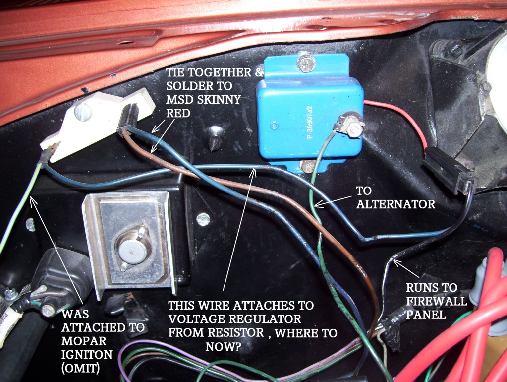
Here's a look at what I have for ignition wiring. Not sure what to do with the wire going from the resistor to the regulator? Trying to figure out how to check for voltage at start position while I'm in the car turning the key? (2 man job?)
04-21-2012, 10:18 AM
#7
Super Moderator
Tie all three of them together with the small red going to the MSD box. Or the wire on the left side can go away if the black wire that connects to the voltage regulator is 12 vdc any time the ignition is on either run or start.
04-21-2012, 10:42 AM
#8
Brem essentially has it right. I believe the "black" must have been painted and is really BLUE, so it would be:
The BLUE coming from the regulator to resistor is "IGN run"
The BROWN is bypass circuit.
Tie that blue and that brown together and hook to MSD "small red"
It appears to me that green? on left side of ballast gets removed
Where does the blue on right side of ballast go? Should go to coil? Is so, it gets omitted.
04-21-2012, 11:43 AM
#9
Mopar Fanatic
Thread Starter
Brem essentially has it right. I believe the "black" must have been painted and is really BLUE, so it would be:
The BLUE coming from the regulator to resistor is "IGN run"
The BROWN is bypass circuit.
Tie that blue and that brown together and hook to MSD "small red"
It appears to me that green? on left side of ballast gets removed
Where does the blue on right side of ballast go? Should go to coil? Is so, it gets omitted.
The BLUE coming from the regulator to resistor is "IGN run"
The BROWN is bypass circuit.
Tie that blue and that brown together and hook to MSD "small red"
It appears to me that green? on left side of ballast gets removed
Where does the blue on right side of ballast go? Should go to coil? Is so, it gets omitted.
04-21-2012, 04:30 PM
#10
Mopar Fanatic
Thread Starter
Just want to veerify this.....the distributor wires (see pic) are gray and black. The MSD installation diagram shows them as being ORANGE and black. Do I just asume the gray wire is the orange wire and keep black to black when connecting the purple and green MSD wires to the distributor?

04-21-2012, 08:30 PM
#11
If the MSD destructions show the wires according to the male / female on the connector, I'd go by that
The worst that will happen is that the rotor will be grossly out of phase with the cap contacts, known as "rotor phasing"
You can verify this by taking an old cap, breaking/ sawing/ drilling it so that you can see inside at the no1 tower, and use a timing light to verify that the spark is happening as the rotor is "making contact" with the plug wire tower.
The difference, if you were to reverse the pickup leads, is dramatic
04-21-2012, 08:43 PM
#12
Super Moderator
These wires are routed together in one harness as the magnetic pickup connector. The connector plugs directly into an MSD distributor or crank trigger. It will also connect to aftermarket pickups. The Violet wire is positive (+) and the Green wire is negative (-).
04-22-2012, 05:24 AM
#13
Mopar Fanatic
Thread Starter
 04-22-2012, 09:30 AM
#14
Mopar Fanatic
Thread Starter
OK guys.....got her all wired up, hooked up the battery and turned the key. Started up good, but idled rough.....spiratic pinging heard in exhaust (detonation?) revved it a few times and misses badly. Shut it down as not to damage anything. Any clues? I've read something about rotor phasing? also spark scatter? Magnetic pickup is wired female on dist to green on MSD, which should both be neg, so I don't think that is reveresed. I don't want to run it while in this condition....any ideas where to start?
04-22-2012, 11:02 AM
#15
Mopar Fanatic
Thread Starter
.......I just found the follwing on the MSD sight......should I try switching the magnetic pickup wires?:
"Check the polarity of the magnetic pickup wires of the distributor. Reverse the connectors and check the timing again. For Analog ignitions the correct polarity is whichever orientation gives the most retarded timing. For Digital Ignitions the correct polarity is whichever orientation give the most advanced timing."
"Check the polarity of the magnetic pickup wires of the distributor. Reverse the connectors and check the timing again. For Analog ignitions the correct polarity is whichever orientation gives the most retarded timing. For Digital Ignitions the correct polarity is whichever orientation give the most advanced timing."
Last edited by olibass1; 04-22-2012 at 11:49 AM.
04-22-2012, 01:43 PM
#16
If it was timed OK before, and you have not moved the dist, I'd just try reversing the picup wires, and DEFINATELY heed whatever MSD says
I'd also be VERY tempted to check "rotor phasing" as I outlined above.
Here's a photo of how "one guy" did it. Just use an old cap, and flash your timing light, connected to whatever wire is at the hole. With the vacuum advance disconnected, the rotor should be "just approaching" the contact, and if you have a way (full intake vacuum or pump) of activating the vacuum advance, the rotor should be "about equally" on the opposite side of the contact with the vacuum "all in."
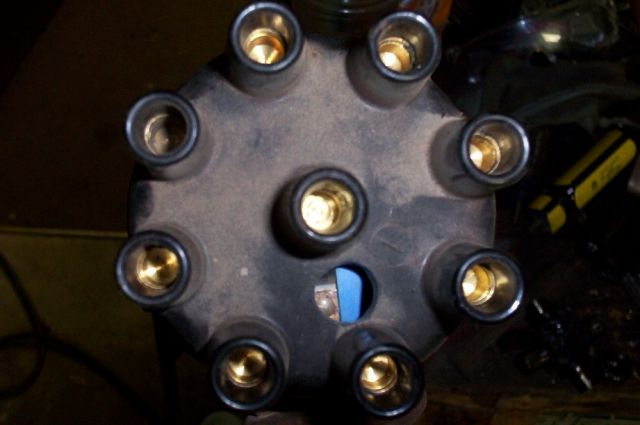
If the reluctor is properly installed (left arrow for BB / RB and 426, right hand arrow for SB) and IF the dist. and reluctor are made correctly, the rotor phase should be OK. The mechanical advance moves the rotor and reluctor together, so they should not change, relative to each other.
If you "Google up" the www, there is lots of info on "rotor phase" / "rotor phasing"
I'd also be VERY tempted to check "rotor phasing" as I outlined above.
Here's a photo of how "one guy" did it. Just use an old cap, and flash your timing light, connected to whatever wire is at the hole. With the vacuum advance disconnected, the rotor should be "just approaching" the contact, and if you have a way (full intake vacuum or pump) of activating the vacuum advance, the rotor should be "about equally" on the opposite side of the contact with the vacuum "all in."
If the reluctor is properly installed (left arrow for BB / RB and 426, right hand arrow for SB) and IF the dist. and reluctor are made correctly, the rotor phase should be OK. The mechanical advance moves the rotor and reluctor together, so they should not change, relative to each other.
If you "Google up" the www, there is lots of info on "rotor phase" / "rotor phasing"
Last edited by 440roadrunner; 04-22-2012 at 01:52 PM.
The following users liked this post:
olibass1 (04-22-2012)
04-22-2012, 02:28 PM
#17
Mopar Fanatic
Thread Starter
If it was timed OK before, and you have not moved the dist, I'd just try reversing the picup wires, and DEFINATELY heed whatever MSD says
I'd also be VERY tempted to check "rotor phasing" as I outlined above.
Here's a photo of how "one guy" did it. Just use an old cap, and flash your timing light, connected to whatever wire is at the hole. With the vacuum advance disconnected, the rotor should be "just approaching" the contact, and if you have a way (full intake vacuum or pump) of activating the vacuum advance, the rotor should be "about equally" on the opposite side of the contact with the vacuum "all in."
If the reluctor is properly installed (left arrow for BB / RB and 426, right hand arrow for SB) and IF the dist. and reluctor are made correctly, the rotor phase should be OK. The mechanical advance moves the rotor and reluctor together, so they should not change, relative to each other.
If you "Google up" the www, there is lots of info on "rotor phase" / "rotor phasing"
04-22-2012, 03:54 PM
#18
Mopar Fanatic
Thread Starter
Swapped the pickup wires and she ran great! Took her out and purred nicely....no misses! My only concern is my altmeter seems to be pulsing. Not sure if it's a big deal, but not sure what's causing it.
Thanks to ALL!
Thanks to ALL!
04-22-2012, 05:21 PM
#19
OK, NOW you need to find out why
Run a couple of tests
Hook one probe of your meter to the battery + post, the other to the regulator IGN terminal.
Turn key to "run" engine off
You are hoping for a VERY low reading, the lower the better, and you are measuring the "voltage drop" in the ignition harness path from
the battery -- fuse link-- bulkhead connector -- ammeter circuit -- ignition switch connector -- through the switch -- back out the switch connector -- back out the bulkhead connector -- to the regulator "I" terminal.
IF this reading is more than 2. - .3V (three TENTHS of a volt) you need to find out WHY. Your top suspects are the bulkhead connector, the igntion switch connector, the switch itself, and the "in harness" factory splice and ammeter circuit.
Next, check the ground side. Run the engine, set engine to a good fast IE "cold" idle to simulate low cruise, and check battery voltage with the engine WARM. It should be close to 14V, 13.8--14.2 is OK, NOT below 13.5, and not above 15
Next, stick one probe of your meter to battery NEG post, and the other directly onto the regulator mounting ear. Be sure to "stab" through any paint, rust, etc
As above, you are looking for a LOW reading, the lower the better. A reading MORE than .2V (two tenths of a volt) means there is not a good ground between battery/ engine block/ car body/ regulator.
If this is OK, put one meter lead on battery positive post, the other on the alternator output stud. See if this is pulsing, and how high is the reading? If the system is charging "hard" it might be approaching 1 volt, but no more. Should be less than 1 volt if the bulkhead connector, harness, and ammeter circuit are OK.
IF all the above checks out OK, check and or replace the alternator brushes, and if that does not help, replace the regulator.
04-22-2012, 05:52 PM
#20
Mopar Fanatic
Thread Starter
OK, NOW you need to find out why
Run a couple of tests
Hook one probe of your meter to the battery + post, the other to the regulator IGN terminal.
Turn key to "run" engine off
You are hoping for a VERY low reading, the lower the better, and you are measuring the "voltage drop" in the ignition harness path from
the battery -- fuse link-- bulkhead connector -- ammeter circuit -- ignition switch connector -- through the switch -- back out the switch connector -- back out the bulkhead connector -- to the regulator "I" terminal.
IF this reading is more than 2. - .3V (three TENTHS of a volt) you need to find out WHY. Your top suspects are the bulkhead connector, the igntion switch connector, the switch itself, and the "in harness" factory splice and ammeter circuit.
Next, check the ground side. Run the engine, set engine to a good fast IE "cold" idle to simulate low cruise, and check battery voltage with the engine WARM. It should be close to 14V, 13.8--14.2 is OK, NOT below 13.5, and not above 15
Next, stick one probe of your meter to battery NEG post, and the other directly onto the regulator mounting ear. Be sure to "stab" through any paint, rust, etc
As above, you are looking for a LOW reading, the lower the better. A reading MORE than .2V (two tenths of a volt) means there is not a good ground between battery/ engine block/ car body/ regulator.
If this is OK, put one meter lead on battery positive post, the other on the alternator output stud. See if this is pulsing, and how high is the reading? If the system is charging "hard" it might be approaching 1 volt, but no more. Should be less than 1 volt if the bulkhead connector, harness, and ammeter circuit are OK.
IF all the above checks out OK, check and or replace the alternator brushes, and if that does not help, replace the regulator.
Run a couple of tests
Hook one probe of your meter to the battery + post, the other to the regulator IGN terminal.
Turn key to "run" engine off
You are hoping for a VERY low reading, the lower the better, and you are measuring the "voltage drop" in the ignition harness path from
the battery -- fuse link-- bulkhead connector -- ammeter circuit -- ignition switch connector -- through the switch -- back out the switch connector -- back out the bulkhead connector -- to the regulator "I" terminal.
IF this reading is more than 2. - .3V (three TENTHS of a volt) you need to find out WHY. Your top suspects are the bulkhead connector, the igntion switch connector, the switch itself, and the "in harness" factory splice and ammeter circuit.
Next, check the ground side. Run the engine, set engine to a good fast IE "cold" idle to simulate low cruise, and check battery voltage with the engine WARM. It should be close to 14V, 13.8--14.2 is OK, NOT below 13.5, and not above 15
Next, stick one probe of your meter to battery NEG post, and the other directly onto the regulator mounting ear. Be sure to "stab" through any paint, rust, etc
As above, you are looking for a LOW reading, the lower the better. A reading MORE than .2V (two tenths of a volt) means there is not a good ground between battery/ engine block/ car body/ regulator.
If this is OK, put one meter lead on battery positive post, the other on the alternator output stud. See if this is pulsing, and how high is the reading? If the system is charging "hard" it might be approaching 1 volt, but no more. Should be less than 1 volt if the bulkhead connector, harness, and ammeter circuit are OK.
IF all the above checks out OK, check and or replace the alternator brushes, and if that does not help, replace the regulator.
04-22-2012, 08:13 PM
#21
Super Moderator
It's simple. It's the voltage it is taking away from the system. It's normal draw that the MSD box is taking. If it runs great then you did a good job and enjoy it.
04-23-2012, 09:09 AM
#22
It's possible that you are experiencing RF interferance between the ignition and the regulator. This is sort of the same as interferance from, say, ignition in your AM radio, except that instead of being able to hear it, it instead affects an electronic device. As the MSD is a fairly high power device, this is very possible.
One thing you might try is to get an RF suppression capacitor (condenser) which you can get at any decent parts store, and put as close to the regulator as you can. This would be a cap like or similar to the original one that was mounted at the coil and hooked to coil +
You might also read around the tech articles at the MSD site, I'd bet there is something on this subject.
04-23-2012, 09:45 AM
#23
Mopar Fanatic
Thread Starter
Where did you hook the "full time hot" wire, IE the one going to unswitched 12V?
It's possible that you are experiencing RF interferance between the ignition and the regulator. This is sort of the same as interferance from, say, ignition in your AM radio, except that instead of being able to hear it, it instead affects an electronic device. As the MSD is a fairly high power device, this is very possible.
One thing you might try is to get an RF suppression capacitor (condenser) which you can get at any decent parts store, and put as close to the regulator as you can. This would be a cap like or similar to the original one that was mounted at the coil and hooked to coil +
You might also read around the tech articles at the MSD site, I'd bet there is something on this subject.
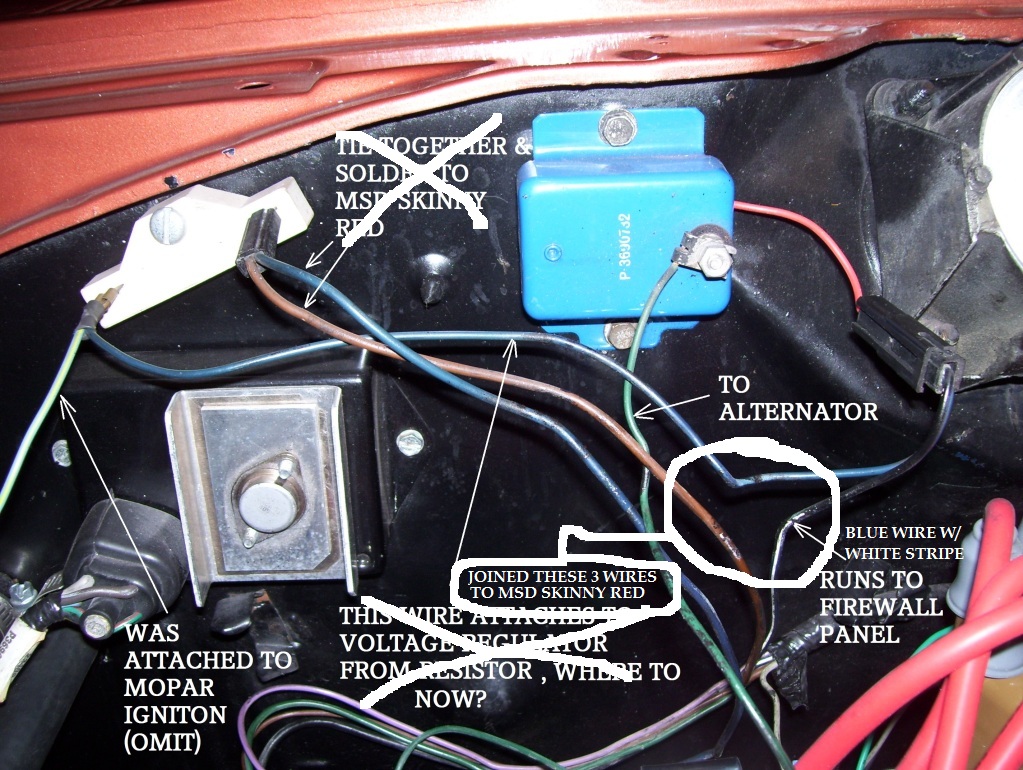
This is how I ended up connecting the wires that were in the original resistor & regulator circuit (see pic below). The blue wire that you see connected to the resistor (with the brown) was running to the coil....that is gone. I did check MSD forum for similar and found one that went on forever......didn't sound like they really had a good answer.
 04-23-2012, 11:58 AM
#24
Mopar Fanatic
Thread Starter
Got this info from a "memeber" (not a tech) on the MSD forum....thinking about trying it. Anyone see any reason why this could not be a good fix?:
Originally Posted by YO7_A66
I swapped out a Mopar style ECU to the MSD Streetfire ignition box and I too had an issue with the ammeter bouncing (& system voltage bouncing) at idle. This is how I fixed it:
"" I added the MSD supplied diode to the SMALL RED wire and I no longer have fluctuations in my ammeter and my voltage gauges at idle. All of my gauges are now solid at idle like they were previous to the Streetfire install.
It appears that something was feeding back thru my RUN circuit when the ignition key was in the RUN mode which affected my alternator, alternator external voltage regulator, my ammeter, two voltage gauges, and my dash lights. The diode fixed it all and now my cars gauges are acting normal with the diode installed.""
As a test, I started the car with the diode in place and ammeter/votage gauges were solid. I then shut off the engine and pulled the diode. I then restarted the engine and my ammeter/voltage gauges were bouncing again at idle. I then shut off the engine and reinstalled the diode. I then restarted the engine and my ammeter/voltage gauges have never bounced around at idle since.
04-24-2012, 04:01 AM
#25
Mopar Fanatic
Thread Starter
Originally Posted by YO7_A66
I swapped out a Mopar style ECU to the MSD Streetfire ignition box and I too had an issue with the ammeter bouncing (& system voltage bouncing) at idle. This is how I fixed it:
"" I added the MSD supplied diode to the SMALL RED wire and I no longer have fluctuations in my ammeter and my voltage gauges at idle. All of my gauges are now solid at idle like they were previous to the Streetfire install.
It appears that something was feeding back thru my RUN circuit when the ignition key was in the RUN mode which affected my alternator, alternator external voltage regulator, my ammeter, two voltage gauges, and my dash lights. The diode fixed it all and now my cars gauges are acting normal with the diode installed.""
As a test, I started the car with the diode in place and ammeter/votage gauges were solid. I then shut off the engine and pulled the diode. I then restarted the engine and my ammeter/voltage gauges were bouncing again at idle. I then shut off the engine and reinstalled the diode. I then restarted the engine and my ammeter/voltage gauges have never bounced around at idle since.[/QUOTE]
Well....that didn't work. My issue is a bit different than the MSD guys, as my other aftermarket gauges (tach & oil pressure) do not bounce or pulse, just the factory altmeter. It moves to the high side when I first start it up , and then starts pulsing at idle after that. I tried moving the mag pickup wires to different areas(intereference) but that did nothing either. I think I will try replacing the regulator and see what happens.
The following users liked this post:
Jackpot50 (06-17-2014)
04-24-2012, 09:15 AM
#26
You really should run the voltage checks I outlined. That regulator you pictured should be a high quality unit. It MIGHT be the problem, but I just HATE spending money on un-needed parts.
There are so many people having troubles with bad harness connections, and most especially the bulkhead connector, that this alone accounts for a large percentage of problems I come across
It was THE main problem when I first got my 67 Dart. There was a ONE VOLT drop in the "ignition run" path from the battery to the resistor/ regulator, and THIS DID cause pulsing.
Mine has now been "pretty much rewired, the ammeter eliminated, and converted to an in dash voltmeter. I also converted mine to a 70 / later alternator / regulator, mainly because I had them "lying around." I didn't even buy 'em new!!
Last edited by 440roadrunner; 04-24-2012 at 09:17 AM.
04-24-2012, 04:21 PM
#27
Mopar Fanatic
Thread Starter
You really should run the voltage checks I outlined. That regulator you pictured should be a high quality unit. It MIGHT be the problem, but I just HATE spending money on un-needed parts.
There are so many people having troubles with bad harness connections, and most especially the bulkhead connector, that this alone accounts for a large percentage of problems I come across
It was THE main problem when I first got my 67 Dart. There was a ONE VOLT drop in the "ignition run" path from the battery to the resistor/ regulator, and THIS DID cause pulsing.
Mine has now been "pretty much rewired, the ammeter eliminated, and converted to an in dash voltmeter. I also converted mine to a 70 / later alternator / regulator, mainly because I had them "lying around." I didn't even buy 'em new!!
There are so many people having troubles with bad harness connections, and most especially the bulkhead connector, that this alone accounts for a large percentage of problems I come across
It was THE main problem when I first got my 67 Dart. There was a ONE VOLT drop in the "ignition run" path from the battery to the resistor/ regulator, and THIS DID cause pulsing.
Mine has now been "pretty much rewired, the ammeter eliminated, and converted to an in dash voltmeter. I also converted mine to a 70 / later alternator / regulator, mainly because I had them "lying around." I didn't even buy 'em new!!
01-31-2013, 06:27 PM
#28
New Member

Join Date: Jan 2013
Posts: 1
Likes: 0
Received 0 Likes
on
0 Posts
I have a 72 w200 440 big block. It has a 6al msd box and mallory dist. I bypassed the bulkhead with a 10 gauge wire and fusible link from the alternator to the battery. I also have an eletric fan, water pump, and fuel pump. all of this was installed on the truck before I got it. Where should the voltage regulator be and how should it be wired to my msd ? My truck runs for about 10 mins with the msd,wp,fan,and fuel pump all running.
02-01-2013, 10:20 AM
#29
I take it from the question that you have changed enough wiring that it no longer works?
Look at this simplified diagram:
http://www.mymopar.com/index.php?pid=31
In the diagram, "ignition 1" and "ignition 2" represent the factory original wires coming from the ign switch, through the bulkhead, to the ballast, which you have probably bypassed. Essentially, these two should not be hooked together, in order to supply voltage in both start and run, to the MSD red (small) power on wire.
This point is ALSO where you should take off (as original) to the IGN terminal of the regulator, AND branch off to one of the field terminals.
You can see that the remaining field terminal goes to the F terminal of the regulator. It is VERY important that you ground the regulator.

Thread
Thread Starter
Forum
Replies
Last Post


