
Replaced Voltage Limiter, Now oil gauge is whack
 03-08-2014, 10:14 PM
#1
Mopar Fanatic
Thread Starter
Replaced Voltage Limiter, Now oil gauge is whack
Okay its been a while but over the winter I bought a rte voltage limiter for my cluster because my gas gauge was broken. I managed to replace the limiter without even pulling out the dash, i just dropped the steering wheel (I didnt know my body could even bend that way!). Anyways I started her up today and my gauge gas seems to work! It reads a quarter of a tank, I'm not sure how much gas is actually in there so this spring will be the real test when i actually fill up the tank. Anyways, I turn the car on and the oil pressure gauge goes from 0 to well past full or high pressure. The previous owner put a set of aftermarket gauges below the dash (temp, oil, batt) and the oil pressure works on that gauge. So do you guys think that the original oil pressure gauge simply isnt hooked up to anything? How difficult would it be to transfer the oil cable going to the aftermarket gauge back to the stock gauge?
I just cant wait for spring to roll around, screw snow!
I just cant wait for spring to roll around, screw snow!
 03-09-2014, 07:21 AM
#2
Mopar Lover

More than likely the previous owner took the oil sending unit out to put the after market mechanical gauge with a tube in its place...Usually the after market gauges are mechanical/plumbed gauges and the stock gauge is electric/sending unit type gauges...Hope this helps...The oil port is back by the distributor on a small block (I think I remember you have a 318) if you look there and see a small tube you have a mechanical gauge and if you see a sending unit with wires it is electric..You can have both with a tee or Y fitting if you perfer....Bill Keep us posted!!!
Last edited by pro-tech; 03-09-2014 at 07:24 AM.
 03-09-2014, 09:53 AM
#4
Mopar Fanatic
Thread Starter
Okay I do have a mechanical gauge. i followed the oil tube from the gauge to the back of the block. If I were to switch back to my stock gauges, how difficult of a process would it be to put an electrical oil sender in? would I have to pull the cluster or do you think i could just sneak my hand back behind?
03-09-2014, 12:27 PM
#5
Mopar Lover
No just go to the parts store and tell them you want an oil sending unit for a 74 RR with a 318 with a gauge...(And a good parts person will know that a sending unit is for a gauge anyway and a oil pressure switch is for a light. but most are not very good...Ill say no more) remove the oil tube and fitting install sending unit the wire should still be there (hopefully) If you want both it is just a matter of getting an 1/8" pipe thread Y or T fitting...Male to go into the block and 2 female fittings coming out to screw the sending unit in one and the gauge tube in the other...I would keep the mechanical gauge they are more accurate and true...Bill
03-09-2014, 08:29 PM
#6
Mopar Fanatic
Thread Starter
I did not see any wire that would connect to the sending unit, but ill have to check to see if i can follow any wires back, and if not hopefully i can buy one of those and attach it without too much difficulty. I'm not sure if i would leave the mech oil sender in because i kinda wanted to get rid of the after market gauges because they are just a wiring mess, and then i would have 2 temps, 2 batt, and 2 oil gauges. I just find it a little unnecessary.
07-10-2014, 08:20 PM
#8
Mopar Fanatic
Thread Starter
Hey I'm back and i just bought a shop manual. So now my gas gauge doesnt work anymore and the needle of my oil gauges doesn't move so im thinking that it has a faulty ground wire. I want to fix all of my gauges, temp, batt, oil, and gas. I want to get rid of the aftermarket gauges so i need to fix all the factory ones. I need to buy a oil sending unit, maybe one like this: http://www.ebay.com/itm/Engine-Oil-P...48e6bd&vxp=mtr
I might also have to order the wire that connects it to my bulkhead or gauge.
I'm not even sure if the batt and temp gauges are hooked up but I'm going to pull my dash and work on it this weekend. Is there a way i can fix and test all of my gauges when i have my cluster pulled?
I might also have to order the wire that connects it to my bulkhead or gauge.
I'm not even sure if the batt and temp gauges are hooked up but I'm going to pull my dash and work on it this weekend. Is there a way i can fix and test all of my gauges when i have my cluster pulled?
07-11-2014, 08:47 AM
#9
That sending unit you pictures is for a WARNING LIGHT, and not a gauge. ALL gauge type sending units are a "big can."
You can easily test your cluster out of the car. Get the shop manual. Identify where switched ignition connects into the cluster, coming from the ignition switch. you can FOLLOW the traces on the PC board just by looking at them.
This power coming from one of the connector pins will have a trace leading directly to the terminal of the instrument regulator
Get yourself some resistors. The sender test resistors are
L = 73.7 Ohms (empty)
M = 23.0 Ohms (1/2)
H = 10.2 Ohms (full)
These are the same for fuel, oil, and temp. Example, a 10-12 ohm resistance from the sender terminal of the gauge to ground, with the IVR powered (after about a minute) should give you "full scale" on any gauge they are hooked to
You can go to Radio Shack, EG, and buy a "4 pack" of 100 ohm, 1/2 watt resistors. Hook all 4 in parallel. This will give you a 25 ohm resistor (close enough) to test "half scale" on your gauges
Post a GOOD CLEAR photo you your cluster when you get it removed, it will make it much easier to step you through all this
07-11-2014, 08:47 AM
#10
Also be aware of some of the troubles you face, and what I'm about to type VARIES with car model, as some clusters are different
1........I try to preach to you guys to treat these as an "end to end" system, rather than thinking about "1 thing" think about the entire system and problems you might have. Low voltage, poor connections at the connectors, and so on
2.......Grounding of Mopar clusters has traditionally been "accidental" It's a good idea to hook a ground pigtail to one of the PC board screws, and bring it out so you can bolt it, say, to the column support
3....."What all was wrong" on my 67:
A.........Some of the PC board electrical pins were loose or broken clear off. You need to repair these. In my case I soldered pigtails to the board traces, brought the pigtails out, and converted the harness connector to "Molex" style connectors
B.......The IVR was bad. I bought an RTE
C......The IVR "socket" is spring fingers pressed into the board. These were not making contact with the BOARD TRACES and I had to solder wires across
D.....The fake nuts were not making contact between the gauge studs and the PC board. Replace with real buts and loosen / tighten several times to "scrub" the contact clean
E.....Clean the board (eraser, etc) around you lamp sockets. Bend the socket spring contacts, or replace the sockets. Inspect, clean, replace as necessary. Good idea to replace all bulbs
"Something new" that has come up is a FUEL GAUGE CALIBRATION unit. For "repop" fuel senders which are not accurate read this:
http://www.forabodiesonly.com/mopar/...=264543&page=2
Towards the last of the thread, "we" discover a commercial unit being sold:
Scroll down to post 96
http://www.forabodiesonly.com/mopar/...0&postcount=96
Last edited by 440roadrunner; 07-11-2014 at 08:56 AM.
07-11-2014, 03:58 PM
#11
Mopar Fanatic
Thread Starter
Alright, I just picked up a steering wheel puller and the oil gauge sender. I'm going to start pulling the cluster out tonight.
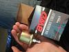
Does this look right? I was reassured that it was for the gauge not the light.
I'm sure there will be more questions to come.

Does this look right? I was reassured that it was for the gauge not the light.
I'm sure there will be more questions to come.

 07-11-2014, 08:12 PM
#13
Mopar Fanatic
Thread Starter
Okay the radio is off now. Now I want to test all of the gauges to see if they work. 440 or anyone, could you explain to me how to test each gauge? I'm a beginner so the more explaination the better. Thanks
Hmm I guess I don't have any of that circuit board like yours 440.
Hmm I guess I don't have any of that circuit board like yours 440.


Last edited by 74Runneer; 07-11-2014 at 08:34 PM.
07-11-2014, 09:10 PM
#14
Turns out a "non Ralley" cluster uses a PC board, and a "Ralley" cluster does not
Go here, and download a 73 factor shop manual.......for free........
http://www.mymopar.com/index.php?pid=31
On this page
http://www.mymopar.com/index.php?pid=109
in two files, the 73 Dodge body manual, and the 73 Dodge chassis manual. The reason for this..........even if you have a 74 manual........is that Ma changed the way the 74 electrical diagrams are illustrated, and there is not (I can't find) an illustration of your Ralley dash as such
In the 73 manual, turn to page 8-135. This is the under--dash diagram for 73 R-W carlines (Charger, B body,) Ralley cluster. If you have tach or clock, refer to the Accessory diagram.........but appears you do not.
So start by carefully reviewing these diagrams and be sure you have the harness all "down" as to how it connects
Then get your "good" instrument regulator. You can hook everything up with clip leads. Follow along
Look at the diagram, and notice that there is a separate little piece of harness that goes from the terminal on the IVR marked (on the diagram) "5V" jumpers over to one terminal of the temp gauge, and over to one terminal of the oil gauge. I do NOT understand why it does not also jumper down to one terminal of the fuel gauge below.
CHECK WITH YOUR ohmeter between those two terminals....on the oil and the fuel gauge........do you show close to zero ohms? If so, they are connnected internally and that is why there is no jumper.
If this checks out, hook your jumper up
Now lay it out on a bench, with a charged 12V battery. Use clip leads, which you can get from Radio Shack
Hook everything up except the 12V + to the battery
Hook a red to the terminal of the IVR marked 12V in the diagram.
Take one of your test resistors I mentioned earlier, say the 23-25 ohm one, and select a gauge at random. Clip to the gauge terminal NOT hooked to the IVR and hook the other end of the lip lead to the resistor. Use a second clip lead to ground the other lead of the resistor to the GROUND connection of the cluster, up there by the IVR
Hook this connection to battery NEG
Now you should have everything hooked up except battery +. Hook this up, and watch the gauge to which you hooked the resistor. In about a minute, if the IVR is good, if the gauge is good, if you got the correct resistor, AND hooked everything up correctly, the gauge should give you very very close to a 1/2 scale (dead in the middle) needle reading
Last edited by 440roadrunner; 07-11-2014 at 09:24 PM.
The following users liked this post:
74Runneer (07-11-2014)
07-11-2014, 09:26 PM
#15
When you decide to check the fuel gauge, make CERTAIN that you hook the resistor to the OPPOSITE side that is (if it is) jumpered to the oil gauge. The way to tell is that the two jumpered terminals.......if they are........will show a zero reading.
The following users liked this post:
74Runneer (07-11-2014)
07-11-2014, 10:15 PM
#16
Mopar Fanatic
Thread Starter
Okay I just downloaded the manuals. Im going to run to radio shack tomorrow to get everything that i need to test the gauges. I dont have any test leads, so how many do i need to get? And for the resistors, do i only need the 4 100 ohm resistors that will give me the 25 ohms, or do I need to find a combo for a 10 and 73 ohm resistance? I have a multimeter/ohmmeter. Is there anything else that i will need?
Also, for the IVR, is the right one the 12V and the left one the 5V? The middle prong on mine is hooked up to some cylinder, is that normal?
I think I understand what to do for the most part, but im a little confused on where to put the leads/resistors. Ill start out by making sure the oil and fuel gauges are internally connected.
Thanks for helping me, I really appreciate it!
 07-12-2014, 09:25 AM
#18
Can I just use the wire that came with the factory cluster instead of using the test leads?
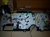
Here the set up Attachment 8974
Here the set up Attachment 8974
07-12-2014, 09:27 AM
#19
RS sells them by the bag. I would buy one of the largest size, and one of the next one smaller. I believe there are three sizes. You should have some, for troubleshooting, "in general."
I would get at the very least middle and "full" scale. They sell not sure, 1/8? watt, 1/4 and 1/2, and some larger power resistors. These gauges do draw some current, so 1/2 watt or larger, I would think.
Figuring resistors in parallel gets tricky. If you Google, there are formulas. Just two is fairly easy. Here's an online calculator
http://www.sengpielaudio.com/calculator-paralresist.htm
If you have 2 or 3 or 4 identical resistors in parallel, it's simply 1/2, 1/3, or 1/4 the original value, as in our 100 ohm setup
Series resistors, you simply add the resistances up
Also, for the IVR, is the right one the 12V and the left one the 5V? The middle prong on mine is hooked up to some cylinder, is that normal?
I think I understand what to do for the most part, but im a little confused on where to put the leads/resistors. Ill start out by making sure the oil and fuel gauges are internally connected.
Thanks for helping me, I really appreciate it!
Look at the diagram and what you have hooked up. The terminal for the jumper is the 5V, the one "with the cylinder" (this is a radio noise capacitor / condenser) is the 12V coming in from the key Ignore what I posted about internal connections. It's obvious from your photo of the harness, that the diagram left this out
Figuring resistors in parallel gets tricky. If you Google, there are formulas. Just two is fairly easy. Here's an online calculator
http://www.sengpielaudio.com/calculator-paralresist.htm
If you have 2 or 3 or 4 identical resistors in parallel, it's simply 1/2, 1/3, or 1/4 the original value, as in our 100 ohm setup
Series resistors, you simply add the resistances up
Also, for the IVR, is the right one the 12V and the left one the 5V? The middle prong on mine is hooked up to some cylinder, is that normal?
I think I understand what to do for the most part, but im a little confused on where to put the leads/resistors. Ill start out by making sure the oil and fuel gauges are internally connected.
Thanks for helping me, I really appreciate it!
Last edited by 440roadrunner; 07-12-2014 at 09:37 AM.
07-12-2014, 09:51 AM
#20
Mopar Fanatic
Thread Starter
Yeah the formula for resistance in parallel is 1/((1/x)+(1/y)+(1/z)). Ill figure something out. But do they just sell 25ohm 1/2 watt and 75ohm 1/2 watt resistors? I'm going to run to radio shack around 5:30 central today.
Is there a way to test all the bulbs that are still connected to the harness inside the car?
Is there a way to test all the bulbs that are still connected to the harness inside the car?
07-13-2014, 10:13 AM
#22
Mopar Fanatic
Thread Starter
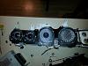
Okay so I hooked it up how I though it should be using the 22 ohm resistor connected to the oil gauge, and I hooked it up to the battery and the gauge went all the way up and was pinned. Here's my set up.
Red went to positive and black went to negative. Green goes from oil to resistor. Yellow goes from resistor to ground. What am I doing wrong?

Red went to positive and black went to negative. Green goes from oil to resistor. Yellow goes from resistor to ground. What am I doing wrong?
07-13-2014, 11:58 AM
#23
Mopar Fanatic
Thread Starter
So now i tried a different method, I skipped the ivr and hooked a 9v battery to the gauge and had the resistor on the opposite peg. This worked for my fuel gauge for all resistors, full, half, and empty. The oil gauge needle was in the middle for the 10 ohm resistor and at 1/4 for the 22 ohm one. for the temp gauge, the 10 ohm about 3/4 and the 22 read about 1/4. Does this mean i have a bad oil and temp gauge? Is there a way to calibrate them?
Last edited by 74Runneer; 07-13-2014 at 02:07 PM.
07-13-2014, 03:31 PM
#24
Okay so I hooked it up how I though it should be using the 22 ohm resistor connected to the oil gauge, and I hooked it up to the battery and the gauge went all the way up and was pinned. Here's my set up.
Attachment 8975
Red went to positive and black went to negative. Green goes from oil to resistor. Yellow goes from resistor to ground. What am I doing wrong?
Attachment 8975
Red went to positive and black went to negative. Green goes from oil to resistor. Yellow goes from resistor to ground. What am I doing wrong?
OR I cannot tell, you sure the IVR is hooked right.
Other than that, the IVR is bad
07-13-2014, 03:34 PM
#25
So now i tried a different method, I skipped the ivr and hooked a 9v battery to the gauge and had the resistor on the opposite peg. This worked for my fuel gauge for all resistors, full, half, and empty. The oil gauge needle was in the middle for the 10 ohm resistor and at 1/4 for the 22 ohm one. for the temp gauge, the 10 ohm about 3/4 and the 22 read about 1/4. Does this mean i have a bad oil and temp gauge? Is there a way to calibrate them?
If the resistor does not change value, it's also possible that the 9V battery is not keeping up. Check battery voltage with your meter to be sure the 9V is not sagging.
Otherwise
If the 9V battery is staying "up"
If the resistor is not changing value
if your connections are good
AND if you have waited "about a minute" for the gauge to stabilize, then one or more is out of cal.
07-13-2014, 04:05 PM
#26
Mopar Fanatic
Thread Starter
Is there a way that I can test the ivr? its brand new and is a solid state so its not supposed to burn out or antrhing like that.
07-13-2014, 04:20 PM
#27
Mopar Fanatic
Thread Starter
What is the wattage of these resistors. If you have an ohmeter that is fairly accurate, re-measure your test resistors to be sure they have not changed value due to heat.
If the resistor does not change value, it's also possible that the 9V battery is not keeping up. Check battery voltage with your meter to be sure the 9V is not sagging.
Otherwise
If the 9V battery is staying "up"
If the resistor is not changing value
if your connections are good
AND if you have waited "about a minute" for the gauge to stabilize, then one or more is out of cal.
07-13-2014, 04:45 PM
#28
Mopar Fanatic
Thread Starter
I think I'm hooking it up wrong. I can't get anything to read correct anymore. The 9v battery drops down to 3.8 when its hooked up. And I switch batteries and the second one I used pinned all the gauges.
07-14-2014, 08:46 AM
#29
9V batteries have VERY limited current output. You must remember that a 9V battery is essentially taking several tiny batteries and wiring them in series. The amperage output is very low, a fraction, EG if you were to make up a 9V by wiwering up AAA batteries, the AAA 9V would blow away a conventional 9V in current and longivety.
Is your IVR marked in any way? If you are sure that you
have 12V into the correct connector
It MUST be grounded to your battery!!
and it it won't give you the results you expect, then the IVR or the gauge is bad
What you could do.
Hook up the "empty" resistor, the 73 ohm. Pick the gauge that reads lowest on your battery. What does it do on the IVR? Does it peg? If not and if it does not read correctly, hook your meter onto the IVR--to gauge terminal, and to ground and read the voltage output. If this is a solid state IVR, it should read close to 5 volts or a shade more.
Also CHECK your test resistors, I would guess you did that.
If the gauges have been operated "pegged" for any length of time due to a failure (of say, the IVR) they may be damaged
07-14-2014, 03:23 PM
#30
Mopar Fanatic
Thread Starter
So is a 9v battery bad for testing? I need to figure out my ivr. My ivr is marked ing on the right side. Thats the side that I have the 12v plugged into. It has to be right because the left side has a special plug for that black wire. I'm going to call rte and ask them about it because its a brand new limiter and they should be able to walk me through how to test it. I checked the resistors, they are accurate.


