No Fire when turning over
 05-19-2013, 12:28 PM
#1
New Member
Thread Starter

Join Date: May 2013
Posts: 1
Likes: 0
Received 0 Likes
on
0 Posts
No Fire when turning over
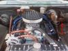
My dad and I have been restoring a 70 Cuda with a 440. We took apart the engine to fix the oil leaks but now it won't fire. There is power running to the coil and ECU box and through the wires from the ECU box to the distributor until we crank over the engine and the testing light goes out. My dad and I are both lost and any help would be appreciated.
 05-20-2013, 01:59 AM
#2
Admin
Welcome!
Have you checked for spark while cranking it? Some items will lose electrical power when turning the motor over. I'm not very good at electrical issues but there are others here who are.
Have you checked for spark while cranking it? Some items will lose electrical power when turning the motor over. I'm not very good at electrical issues but there are others here who are.
05-20-2013, 04:29 AM
#3
Mopar Lover

Welcome to the forum... There are better electricians on here than me so I'll let them reply.... Be sure to check out the Mopar of the Month contest....
05-20-2013, 05:19 AM
#4
Mopar Lover

This might help: http://www.abodyjoe.com/pictures/Mis...erv%20Man1.pdf
 05-20-2013, 06:49 AM
#6

Does the wiring "look" OK, or is it rather hacked up? It SOUNDS from your description that you are not getting power during cranking
Try checking the spark with a wire and plug "rigged" directly to the coil, and under two differing conditions
A--First check by cranking using the KEY
B--Next turn the key to "run" and crank by jumpering the start relay. Just use a screwdriver to jumper between the two large exposed terminals on the relay.
It is important to understand how Mopar ignition voltage is supplied, which is unique, IE different from Ferd/ GM
There are several SEPARATE switches inside the can that we call the "ignition switch"
1--accessory, hot in "run" or "accessory," not part of this issue
2--"IGN 1" or "igntion run", traditionally dark blue, and hot ONLY in "run." This supplies power to the cluster gauges, warning lamps, ignition system, the alternator field (blue) and the regulator IGN terminal, to the idle solenoid if used, and to the electric choke if used, and a couple of smog du dads on some cars. AGAIN IMPORTANT, this is hot ONLY in "run."
3--"IGN 2" the bypass circuit, traditionally brown, is a separate switch contact with a brown wire going out to the coil + side of the ballast resistor. This is hot ONLY in "start" and is the ONLY supply voltage to ignition with the key in "start."
4--"start" the start wire going to the start relay, traditionally yellow, is yet another separate switch contact, a wire going out to the start relay, and is hot only in "start."
So if you get some (maybe weak) spark when jumpering the start relay, but not when using the key, the ballast resistor may be bad (if it's a 4 terminal) or the brown wire may be loosing connection in the bulkhead connector, or problems at the ignition switch connector or in the switch.
What do you have in the way of a shop manual / wiring diagram?
You can find somewhat usable diagrams at MyMopar:
http://www.mymopar.com/index.php?pid=31
two diagrams:
These are NOT ALWAYS complete or accurate!!!!!
http://www.mymopar.com/downloads/1970/70BarracudaA.JPG
http://www.mymopar.com/downloads/1970/70BarracudaB.JPG
or you can download a complete factory shop manual. You WILL have to play with page numbers, as it shows consecutive numbers in your viewer, rather than the "dash" numbering system via Mopar
http://www.mymopar.com/downloads/ser...ice_Manual.zip
Also from this site are simplified wiring for the older 5 pin ECU (4 pin resistor) and the newer 4 pin ECU (2 terminal resistor)
What is NOT shown on these diagrams is the brown bypass wire, which hooks to the end of the ballast which also goes to coil+
http://www.mymopar.com/downloads/Ign...ystem_5pin.jpg
http://www.mymopar.com/downloads/Ign...ystem_4pin.jpg
Last edited by 440roadrunner; 05-20-2013 at 06:55 AM.

Thread
Thread Starter
Forum
Replies
Last Post


