When you click on links to various merchants on this site and make a purchase, this can result in this site earning a commission. Affiliate programs and affiliations include, but are not limited to, the eBay Partner Network.
Hello, I would like to learn and understand the vehicle wiring diagram for my truck. Is there anyone here willing to look at this with me and help to read it so that I can diagnose a no crank issue.
Im not interested in simply replacing parts that may or may not fix the problem
Thank you
First when diagnosing any electrical issue make sure you start with a known good battery that is fully charged. Meaning the voltage should be around 12.5 to 12.6 volts across the battery terminals.
Is this truck equipped with an automatic transmission? If so, the first thing I would check for is a misadjusted neutral safety switch.
If the engine won't crank in Park try cranking it in neutral. Or try holding the key in the crank position while slowing sweeping the shifter through the positions. If the starter engages you know you have a neutral safety switch issue and should try adjusting your shifter linkage.
If this doesn't work we'll move to the next stage of testing.
First when diagnosing any electrical issue make sure you start with a known good battery that is fully charged. Meaning the voltage should be around 12.5 to 12.6 volts across the battery terminals.
Is this truck equipped with an automatic transmission? If so, the first thing I would check for is a misadjusted neutral safety switch.
If the engine won't crank in Park try cranking it in neutral. Or try holding the key in the crank position while slowing sweeping the shifter through the positions. If the starter engages you know you have a neutral safety switch issue and should try adjusting your shifter linkage.
Thank you very much for your offer. I hope that you will not have an issue with this possibly turning into a dragged out topic?
I will do my best to respond as quickly as possible
There are some days though that I may not be able to do much with the truck, my wife has some minor health issue�s that I need to support her on.
I can answer your questions tonight and will do so.
I really am very anxious to understand wiring schematics, I have experience with flow charts pertaining to military diesel but little experience with gas civilian
BTW I have done the sweep and no change
I will describe in better detail
Hello, yes automatic
Turn the key to crank position and absolutely nothing happens most of the time, it actually did engage the starter once
Most of the time the oil light does come on when key is turned to run position but it�s been known to not come on for hours at a time and then all of a sudden light up
Everything else on truck works with exception of horn which hasn�t worked in years and the fuse for taillights is blown
Checked all other fuses with test light
Turn signals work for R turn but extremely slow, I hear nothing for l turn
We have jiggled wiring under hood and inside cab looking for a difference but found none, we have pulled apart the bulkhead connector on firewall and see no excessive corrosion
I had assumed that it was a starter relay so I�ve replaced battery, battery cables and the relay.
The starter does engage by using a screwdriver across the terminals of the solenoid
Someone on another forum suggested it may be a NSS, they suggested that I run a ground wire from the terminal of the relay that the relay gets its ground from over to the negative battery terminal to check for a bad ground on the relay, I did this and no difference
Replaced NSS and no difference so I put the old one back in
I will scan and post good pictures of the wiring diagram tomm evening
I would like to better understand how to read the diagram. I�d like to be able to test multiple locations within the starting system so that I can be educated on what I should expect to see
Is it safe to assume that I will need to get my seldom used multimeter out, at this point I�ve made some basic checks with a test light
There are many online resources for learning to read wiring diagrams. (like here and here). Many automotive service manuals often have a wiring schematic symbol legend.
When I was in automotive trade school they taught us to print out a wiring schematic and then use colored pencils to trace the circuit we're interested in.
There was a color code we used to keep track of the different parts of a circuit. This made it easier to not get lost or confused.
Red = POWER (hot) AT ALL TIMES
(Battery Hot)
Orange = POWER WHEN CIRCUIT IS COMPLETE
(Switch controlled hot)
Green = GROUND AT ALL TIMES
Yellow = GROUND WHEN CIRCUIT IS COMPLETE
(Switch controlled ground)
Blue = ANALOG/VARYING VOLTAGE
(e.g. Voltage from a throttle position sensor or dimmer switch)
Purple = DIGITAL SIGNAL
(e.g. Pulsed signal from an ABS wheel sensor or crankshaft position sensor)
I attached a schematic I edited to show this practice for the control side of the starter relay. If you can print this in color, it will be easier to read.
When looking at a circuit you may not know what everything does so start with the easy stuff first.
We know the starter relay is commanded ON by using a switch and that switch must have power at all times on one side.
So I trace red from the battery > AMP gauge > ignition switch. Hot ALL the time.
Now I noticed the switch and starter relay are connected with a wire.
So I trace Orange from the relay back to the switch. Hot when circuit is complete
I notice the relay is connected to a neutral safety switch. I notice the safety switch has two other wires going to it. They go to the backup lights, so I don't care about them.
Since the ignition switch already supplies the positive, this safety switch must supply the negative (aka ground) to the starter relay coil. Another clue is the terminal of the relay is labeled "G". This ground is through the casing of the transmission itself. So, I also draw a ground symbol.
So, recap. RED There should be power between the battery and ignition switch at all times. ORANGE There should only be power between the ignition switch and relay when the ign. switch is closed. YELLOW There should only be ground between the relay and neutral safety switch when the switch is closed (Park or Neutral). GREEN The neutral safety switch itself should always be grounded because it is screwed into the side of the transmission case which is grounded.
With this information you can confirm power and ground at the starter relay using a test light or voltage meter.
Well, if the starter works by jumping the B+ terminal to the S terminal down on the starter itself. That would make me think either the starter relay isn't working or you have a high resistance/open circuit condition between the starter relay "S" terminal and the starter solenoid "S" terminal via the Brown wire.
Lets try using a test light.
First I always make sure my test light works before use by connecting it across the battery.
Check for 12V at the starter relay.
Connect clip side to battery negative. Disconnect the orange wire from the starter relay and connect it to the test light. When the key is turned to the crank position the test light should turn on.
Now check for ground at the starter relay.
Connect the clip side to battery positive. Disconnect the Dark Green/White wire from the starter relay and connect it to the test light. If the shifter is in the Park or Neutral position the light should turn on.
Thank you, I look forward to running these tests and will report back when I do
Well, if the starter works by jumping the B+ terminal to the S terminal down on the starter itself. That would make me think either the starter relay isn't working or you have a high resistance/open circuit condition between the starter relay "S" terminal and the starter solenoid "S" terminal via the Brown wire.
Lets try using a test light.
First I always make sure my test light works before use by connecting it across the battery.
Check for 12V at the starter relay.
Connect clip side to battery negative. Disconnect the orange wire from the starter relay and connect it to the test light. When the key is turned to the crank position the test light should turn on.
Now check for ground at the starter relay.
Connect the clip side to battery positive. Disconnect the Dark Green/White wire from the starter relay and connect it to the test light. If the shifter is in the Park or Neutral position the light should turn on.
I made sure light lit up using positive post, I assumed you wanted me to disconnect the plug and test it, we did this whilst holding key in start position, the light did nothing I put the plug back onto the relay and same result I stopped here because I was unsure if I should carry out the other test
Just for the heck of it I disconnected the green white wire from starter relay, placed my clip of test light onto positive battery terminal, placed top of test light into the end of plug mentioned above and it lit up immediately
I also ran it through the task of shifting and the light turned out immediately
I am grateful to have found someone that could help me with these tests.
Point of possible interest is that once again the dash oil/idiot light is not coming on this morning when the key is turned to run position
All the gauges jump but that oil light has a mind of its own
Looks like you found your issue. You starter relay is not getting power. Next place I would check is at the ignition switch connector under the dash. The same orange wire should be there. You have to leave it connected for the test. See if you can back probe that wire on the connector using a t-pin and then touch your test light to it while the clip is connected to something metal that has a good ground. If you don't get a light when turning the key the "crank" position, then issue is most likely with the ignition switch it self.
Pull the connector apart and inspect the pins for damage. Reconnect make sure all pins are fully seated. And retest for power.
I had to check a newer wiring diagram. The pink wire connects to the ignition coil. It bypasses the ballast resistor and provides full power to the coil while the starter is engaged.
Don't worry about the oil light for now. It's an unrelated circuit. We'll get to it later.
Looks like you found your issue. You starter relay is not getting power. Next place I would check is at the ignition switch connector under the dash. The same orange wire should be there. You have to leave it connected for the test. See if you can back probe that wire on the connector using a t-pin and then touch your test light to it while the clip is connected to something metal that has a good ground. If you don't get a light when turning the key on, then issue is most likely with the ignition switch it self.
Pull the connector apart and inspect the pins for damage. Reconnect make sure all pins are fully seated. And retest for power.
I had to check a newer wiring diagram. The pink wire connects to the ignition coil. It bypasses the ballast resistor and provides full power coil while the starter is engage.
Don't worry about the oil light for now. It's an unrelated circuit. We'll get to it later.
I do not have the wiring diagram in front of me, I have questions concerning flow, I thought it worth testing the wire that off the top of my head comes directly from the dash voltage gauge to presumably the ignition switch. I�d like to understand how to make the proper test before and after the ignition switch
I will do as you have directed and report back in the meantime
Thank you
For our purposes when reading a wiring diagram or thinking of a circuits operation. We use conventional flow. Current flows from positive to negative. Later on it was discovered that electrons actually flow from negative to positive. You can read about that here if you want.
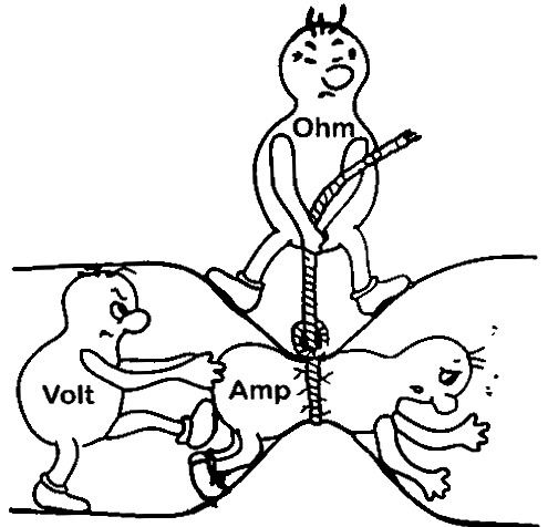
It's also good to understand the relationship between current (amps), resistance (ohms) and voltage.
I wouldn't worry about the voltage gauge but, the amperage gauges however are know for overheating and failing on these trucks but, that usually causes most of the vehicles electrical system to quit working due to high resistance. A good improvement is to bypass the amp gauge to avoid future trouble. I have done this on two of my trucks.
A voltage drop test is a powerful tool when troubleshooting automotive electrical systems. With it you can check for excess loss of voltage across a switch, connector or length of wire.
There are many videos on this subject. I've posted a short and simple one. The specification they give in the video for not exceeding 0.2 volts is a good one but, your truck is also 44 years old, lets cut it some slack. Lets say 0.5 to 0.8 volts instead. The important thing to remember is there has to be current flowing when running the test. For example if you where testing for voltage drop across the headlight switch, the headlights would need to be turned on.
If you wanted to. You can leave one lead at the battery positive terminal. Move the other lead to different parts of the circuit. For example the head lamp connector, then the firewall bulkhead connector, then the low - hi beam selector switch, then headlight switch and etc. So, if you had a 3 volt drop out at the headlights, You could work yourself back in the circuit until the drop went away. This is how you pin point a problem like this. Again use t-pins to backprobe connectors as the circuit must be intact and operating during the test. NEVER use a t-pin to pierce a wires insulation. This will compromise a wire to moisture and lead to corrosion (causing voltage drop). edit: on older vehicles like ours it may be possible to use the tip of the test light directly to touch pins on the back side of the connector. Use your own judgement at what will work best without causing damage.
Now since the cranking circuit requires you to hold the key in the crank position. I figured it would be easier to just use a test light to see if we're getting any useful power out of the "cranking" contacts of the ignition switch.
edit:
Your ignition switch connector can vary depending on if you have tilt or non-tilt steering column.
Looks like you found your issue. You starter relay is not getting power. Next place I would check is at the ignition switch connector under the dash. The same orange wire should be there. You have to leave it connected for the test. See if you can back probe that wire on the connector using a t-pin and then touch your test light to it while the clip is connected to something metal that has a good ground. If you don't get a light when turning the key the "crank" position, then issue is most likely with the ignition switch it self.
Pull the connector apart and inspect the pins for damage. Reconnect make sure all pins are fully seated. And retest for power.
I had to check a newer wiring diagram. The pink wire connects to the ignition coil. It bypasses the ballast resistor and provides full power to the coil while the starter is engaged.
Don't worry about the oil light for now. It's an unrelated circuit. We'll get to it later.
I was able to check what I�m assuming is the orange wire which starts out as yellow on ignition switch side and nothing there when key turned to start position Everything else on this connector lit up on run position with the exception of a black ground wire that again starts at ignition switch
Very strange that things are pointing toward a bad ignition switch since I drove the truck for many years and right up until parking it I NEVER had an issue with the ignition
I found this wiring diagram online, supposedly it is correct for my truck, it�s what I have been using thus far
I have a lot of questions about how to read. I understand that it�s difficult for you to read this using these images
If you would like and be willing I could print one out and mail it to you?
The lines do not line up perfectly throughout diagram. I do not know why but I believe that I have them together close enough
I had an extremely long and well detailed questions sheet typed out, I hit submit and it all disappeared
It kept saying auto save
Is there anyway to retrieve this?
Id like to start at the battery, one cable to starter relay, from starter relay it branches off with 2 cables, one down to starter and the other a S1A-16DB, into fusible link, one wire goes down and is re designated a DSI-10RE which goes to front of the truck, seemingly passes through two unknown connectors and ends up at the diagnostic connector.
Why do the wire designations change, I understand that the colors are displayed on the second half of description but what does description describe?
S1A-16DB changes to aS1-10RE and goes into and out of terminal 5 of bulkhead connector. Same wire goes over to printed circuit board ( page 5 of 6 ) and ends at what they note as ammeter? I have no ammeter, only a voltage regulator and other various gauges?
One wire seemingly goes into printed circuit board / instrument cluster and one wire is shown to exit ( ? )
A20A-10BK leaves ammeter and is split ( directly under headlight switch pg 4 of 6 ) into 5 other wires
First is a A20F-12BK electric door lock provision ( which I do not have )
2nd wire A20C-12BK and goes into connector and out as a BATT 1-12RE and seemingly provides + power to switch
3rd wire is a A20E-12BK/PK and comes out as a ground 18/BK and Im appears to be a ground for ignition switch
4th wire is an A20A-10BK and for some reason changes to an A20-10BK (loses the A ) and goes into and out of terminal 23 of bulkhead connector where it travels onward to batt terminal on Alt ( is this providing + energy to alternator and does that have something to do with exciting the ???? ) ?
5th wire is an A20D-12BK and travels into fuse box where it appears to power stop lamps and also batt accessories
Alot of questions here, is it safe to assume that if I were to have a colored flow of energy chart that I have started and proceeded in the correct place to be able to determine where the issue started?
In other words if I had a better understanding of the image they call printed circuit board and understood why it only shows 2 wires versus the many that I am actually looking at I feel that I would have had a much better chance at tracing a problem
I was able to check what I’m assuming is the orange wire which starts out as yellow on ignition switch side and nothing there when key turned to start position Everything else on this connector lit up on run position with the exception of a black ground wire that again starts at ignition switch
Very strange that things are pointing toward a bad ignition switch since I drove the truck for many years and right up until parking it I NEVER had an issue with the ignition
Yes, it sure is looking like a faulty ignition switch.
If you want to run one more test to confirm. You could disconnect the ignition switch connector from the truck and use your multimeter to measure the resistance ( Ω ) across the BATT 2-12PK/BK (also try BATT 1-12RE) and START 14YE while turning the key... but I'm pretty sure you found the problem.
As I see it you have two options:
Disassemble the steering column and replace the switch. (Special Tools needed: steering wheel puller and snap ring pliers)
or
Install a momentary push button switch to energize the starter relay from inside the cab.
Originally Posted by Dinah
Why do the wire designations change, I understand that the colors are displayed on the second half of description but what does description describe?
I pulled up the service manual over at mymopar.com. It looks like pages 8-148 and 8-149 answer this question.
breakdown of circuit identification codes
Originally Posted by Jason
I had an extremely long and well detailed questions sheet typed out, I hit submit and it all disappeared
It kept saying auto save
Is there anyway to retrieve this?
I'm not sure. I worry about that kind of stuff happening to me so I usually type long messages in a word processor, save it, and then copy and paste the message into a new thread post.
I'll try to post replies to more of you questions when I have time.
Yes, it sure is looking like a faulty ignition switch.
If you want to run one more test to confirm. You could disconnect the ignition switch connector from the truck and use your multimeter to measure the resistance ( Ω ) across the BATT 2-12PK/BK (also try BATT 1-12RE) and START 14YE while turning the key... but I'm pretty sure you found the problem.
As I see it you have two options:
Disassemble the steering column and replace the switch. (Special Tools needed: steering wheel puller and snap ring pliers)
or
Install a momentary push button switch to energize the starter relay from inside the cab.
I pulled up the service manual over at mymopar.com. It looks like pages 8-148 and 8-149 answer this question.
breakdown of circuit identification codes
I'm not sure. I worry about that kind of stuff happening to me so I usually type long messages in a word processor, save it, and then copy and paste the message into a new thread post.
I'll try to post replies to more of you questions when I have time.
I will definitely install an ignition switch, as far as I know tools will not be an issue but I have not experienced this particular column.
I have a factory service manual but it is stored away inaccessible
I see that you mentioned service manual and provided a link, I�ll have to open this on my laptop and assume that there might be some clear instructions there for switch replacement
I think I may remember difficulty with getting the chrome trim ring/ bezel off the original one to transfer to the new one
Im wondering if I could do anything with the original switch as far as I cannot for the life of me imagine that this switch would just suddenly go bad, I�m not sure how this switch is built per se but I have some experience and I keep telling myself that I would have noticed warning signs as the switch wore down
I have a multimeter but have little experience with using it, I will post a picture and hopefully you can walk me through the process of making the final test to confirm that the switch is indeed bad before I get to involved with the project of disassembling this old column
Thank you for your time
I made the tests that you have suggested, I disconnected the ignition harness from the truck, probed the terminals inside plug, first batt 2-12pk/bk ( which btw shows no sign of ever having a black stripe through it ) and the start 14YE and this was my reading I then did the same test on the BATT 1-12 RE and the START 14YE and same result I�ll assume that this still points to a bad switch? Is that correct? Is there any chance that the ignition switch isn�t getting grounded properly? Or ???
I�d hate to get into taking apart column only to find out that I am chasing the wrong part
Ive replaced a lot of ignition switches in stolen vehicles in the past but don�t think that I have ever had much luck with these varieties
Seems to me that swollen pot metal parts make these difficult to work on???? Again that may not even apply to this truck
One thing is for sure and that is the truck is in too nice of shape to not get the correct parts replaced
Appears to be a 3747 192 and looks like it was used on many different vehicles and years The question is to buy OEM from e-bay ( I�ve had rarely issues with OEM returns being resold as new and not working as well ) or get a much cheaper one from parts store locally that may last a short period of time
I made the tests that you have suggested, I disconnected the ignition harness from the truck, probed the terminals inside plug, first batt 2-12pk/bk ( which btw shows no sign of ever having a black stripe through it ) and the start 14YE and this was my reading I then did the same test on the BATT 1-12 RE and the START 14YE and same result I’ll assume that this still points to a bad switch? Is that correct?
OL stands for open loop, overload or over limit. It means there is no electrical continuity between the meter leads, in this case it's an open circuit. We've confirmed the ignition switch "cranking" contacts are not closing.
I forgot to mention just as I make sure my test light works for before use. I usually test my ohmmeter leads. I touch the leads together to measure their resistance. So for example if the leads resistance was 0.3 Ohms I would take note of it. So, if I then measured a cross the primary side of an ignition coil and got 1.8 Ohm, I would know it's really 1.5 Ohms.
Originally Posted by Jason
Is there any chance that the ignition switch isn’t getting grounded properly? Or ???
Looking at the wiring diagram the ignition switch appears to only use ground for some kind of bulb-check/test for the (red) brake light on the instrument cluster.
GROUND 18/BK > B16CBD/WH > B16-18DB/WH > B16A-18DB/WH > F (pin of PCB for BRAKE Light)
So, if the ignition switch didn't have ground, that would be the only function that would not work. The switch connects battery positive to all other circuits.
There are two other switches that can turn on the brake light. The parking brake switch and the brake sentinel switch. I believe the sentinel switch is part of the combination valve and is used to warn the driver of hydraulics issues in the braking system (such as air or a leak).
I tend to avoid messing with the parking brake on automatic transmission vehicles as their often not used enough to prevent them from getting stuck and failing to fully release after being set.
Originally Posted by Jason
I’d hate to get into taking apart column only to find out that I am chasing the wrong part
I believe if you acquired another switch you could connect it and test it outside of the column first.
Originally Posted by Jason
Appears to be a 3747 192 and looks like it was used on many different vehicles and years The question is to buy OEM from e-bay ( I’ve had rarely issues with OEM returns being resold as new and not working as well ) or get a much cheaper one from parts store locally that may last a short period of time
Part #: 3747192 appears to be correct. If you can manage to get a hold of a New Old Stock OEM switch, that is the route I would definitely go. I currently have an aftermarket switch installed in one of my trucks and I'm planning on removing it in the near future because of it's poor quality.
It looks like there is a few switches currently available on eBay.
Hello, I�m gonna make sure my horn and turn signals all work before I put this back together. I�m gonna take it apart as time permits
I would have thought that supplying the little spring loaded button with a good ground from a feeder wire would make the horn function? Is that not true?
I also need to figure out why the R blinker flashes so slow and L blinker does not function at all
Thanks for your time
Correct, grounding out that button should cause the horn to blow.
I believe the ignition switch must also be turned ON because the positive side of the horn is wired to keyed 12V power instead of direct battery power.
However, I would not be surprised if the horn circuit still didn't work due to the fact that Dodge didn't utilize a relay. They tried to make the horn switch itself ground and carry the full electrical load of the horn.
I chose to fix this issue on my trucks by added a relay. So now the horn switch triggers a relay and the relay powers the horn. In fact, on one of my trucks I added two tone horns. I always thought it was odd that these trucks only had the one horn. I also removed the circuit from the key, so the horns can work at all times.
As for the turn signals. While the switch for it can seem complicated, it's easy once you understand how its laid out. But, first lets start with the basics.
There are two flasher cans. One for turn signals and one for hazards.
What happens if you turn on the hazards?
If no change, are bulbs burned out?
When you turn on the hazard switch there are three things that happen:
Power from the hazard flasher gets jumped to the Front Left and Front Right turn signal lamps
The Rear Left and Rear Right signal lamps connection with the brake stop switch is severed.
Power from the hazard flasher gets jumped to the Rear Left and Rear Right signal lamps.
As you can see, the rear signals are a little more tricky because they double as a brake lamp. Even when making a normal left or right signal, the "cancelling cam" first breaks connection with the brake switch before apply power from the flasher. Also, Both the brake switch and hazard switch rely on the "cancelling cam" and it resting in the center position for powering the rear signal/brake lamps.
One important thing to note is parking lamps are done by a separate filament and are not handled by the turn signal or hazard switch.
Thanks for that, I did not want to admit in yesterdays post that I did connect a simple wire from a good ground to that small button and it instantly made the plastic glow red down inside the plastic column where plunger would seat, I�m gonna assume that the spring below the plunger is part of the components and has become weakened due to age and yesterday�s trial pretty much shortened any chance of survival
I do have dual horns, the set up appears unmolested and factory, the truck also has a dual tank setup.
I will try the flashers, did not think of that but I will first have to source some glass fuses because the taillight fuse is blown
Ive thrown away many glass fuses in the past never considering that I would have a shortage yet here I am now probably having to spend ridiculous money on them 😖
Thanks for that, I did not want to admit in yesterdays post that I did connect a simple wire from a good ground to that small button and it instantly made the plastic glow red down inside the plastic column where plunger would seat, I�m gonna assume that the spring below the plunger is part of the components and has become weakened due to age and yesterday�s trial pretty much shortened any chance of survival
It had probably already done that before, that's why it quit working. Either way, it's fine. I've broken my fair share of stuff. All you can do is learn from it.
Anyway, did the plastic melt around the horn contact?
If the plastic is still intact, I would test the contact by disconnecting the ground wires from both horns. I would then connect a test light to one of the ground wires with the clip side connected to battery positive. When you ground out the horn contact, the light should turn on. If it works, I would retest with the steering wheel installed and try with the switch.
If everything checks out the horn contact should be at least good enough to run a relay.
You could also test the individual horns themselves by directly jumping ground to them. Make sure the key is on.
Originally Posted by Jason
I will try the flashers, did not think of that but I will first have to source some glass fuses because the taillight fuse is blown
Ive thrown away many glass fuses in the past never considering that I would have a shortage yet here I am now probably having to spend ridiculous money on them 😖
When does the fuse blow? As soon as it's installed? When you turn on the key? When you turn on the lights?
I am not aware of a dedicated fuse for the taillights and I don't see one on the wiring diagram.
However, both flasher are ran by different fuses. I assume the 20A "T/SIGA GA" fuse is what blew?
I am curious if the fuse for the hazards will blow. (20A HAZARD DOME LP)
If you keep blowing fuses we may need to discuss building a tool that will help save on fuses while tracing the problem.
It had probably already done that before, that's why it quit working. Either way, it's fine. I've broken my fair share of stuff. All you can do is learn from it.
Anyway, did the plastic melt around the horn contact?
If the plastic is still intact, I would test the contact by disconnecting the ground wires from both horns. I would then connect a test light to one of the ground wires with the clip side connected to battery positive. When you ground out the horn contact, the light should turn on. If it works, I would retest with the steering wheel installed and try with the switch.
If everything checks out the horn contact should be at least good enough to run a relay.
You could also test the individual horns themselves by directly jumping ground to them. Make sure the key is on.
When does the fuse blow? As soon as it's installed? When you turn on the key? When you turn on the lights?
I am not aware of a dedicated fuse for the taillights and I don't see one on the wiring diagram.
However, both flasher are ran by different fuses. I assume the 20A "T/SIGA GA" fuse is what blew?
I am curious if the fuse for the hazards will blow. (20A HAZARD DOME LP)
If you keep blowing fuses we may need to discuss building a tool that will help save on fuses while tracing the problem.
I do not think the fuse blowing is any more than a trailer wiring issue that shorted, could be wrong.
I�ll hopefully be back on this tomm
Have a new flasher and fuse
I tested horns and they work fine, the plastic is not melted but I could see it glowing red down in there when I grounded button
Now the plunger spring appears to be collapsed
 01-22-2023, 11:52 AM