
igition switch puzzle - hei mod

Thread Starter
Mopar Fanatic
Joined: Dec 2016
Posts: 294
Likes: 44
From: Kansas
ignition switch puzzle - hei mod
Hey
I'm in the process of converting one of my 1977 W200s over to hei ignition. I have one concern regarding the ignition switch.
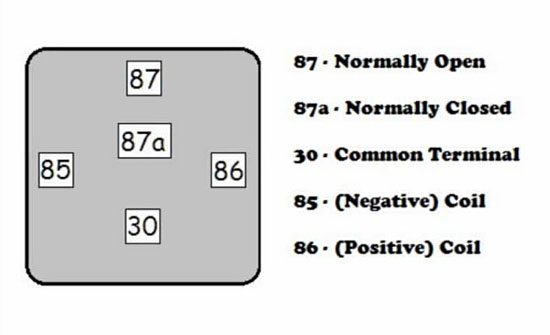
My module and coil are going to be controlled by a 5pin Bosch-style relay. In order for the relay to engage for both the Start and Run position, I will need to join the pink (start) and red (run) wires together for the 85 pin one the relay. This would mean bypassing the ballast resistor which I had planed to remove anyway. Most of the conversions guides I've found tell you to do this, so maybe it's not a problem?
But, I believe joining the two wires would mean the accessories would be backfed power during cranking.. I don't think this is a good thing as the wire involved were never meant to carry that load.
I do have some ideas. (With attached bad doodle drawings)
The first idea would be to leave the stock 1.5 Ohm resister connected a cross the two wires as backfeed prevention appears to be one of it's functions when looking at the diagram. The concern with this is, would the voltage drop effect the reliability of the relay? I suppose the resister could be a diode instead but, I don't know how to properly size one for this application. The diode I have off hand is the RadioShack 276-1661 which is a 50V 6A rectifier diode which I used for the acdelco alternator swap to prevent engine run-on and to protect the trio in the alt itself.
The second idea seems a little over engineered.
Basically I would add another relay and "double" relay the ignition on the Run side. The extra relay would keep the connection between the pink and red open during cranking thus no path for backfeeding to the acc.
So, am I over thinking this? I think I probably am but, I can't help it. I see a potential problem I want to fully investigate it rather than just assume it will be fine.
For example, I sure it would be fine if I connected those wires and called it good because the voltage drop caused by the starter would prevent the accessories from drawing too much current. But, what if the starter failed to engage one day and I happened to have left the wipers and/or heater on?

I'm in the process of converting one of my 1977 W200s over to hei ignition. I have one concern regarding the ignition switch.
My module and coil are going to be controlled by a 5pin Bosch-style relay. In order for the relay to engage for both the Start and Run position, I will need to join the pink (start) and red (run) wires together for the 85 pin one the relay. This would mean bypassing the ballast resistor which I had planed to remove anyway. Most of the conversions guides I've found tell you to do this, so maybe it's not a problem?
But, I believe joining the two wires would mean the accessories would be backfed power during cranking.. I don't think this is a good thing as the wire involved were never meant to carry that load.
I do have some ideas. (With attached bad doodle drawings)
The first idea would be to leave the stock 1.5 Ohm resister connected a cross the two wires as backfeed prevention appears to be one of it's functions when looking at the diagram. The concern with this is, would the voltage drop effect the reliability of the relay? I suppose the resister could be a diode instead but, I don't know how to properly size one for this application. The diode I have off hand is the RadioShack 276-1661 which is a 50V 6A rectifier diode which I used for the acdelco alternator swap to prevent engine run-on and to protect the trio in the alt itself.
The second idea seems a little over engineered.
Basically I would add another relay and "double" relay the ignition on the Run side. The extra relay would keep the connection between the pink and red open during cranking thus no path for backfeeding to the acc.
So, am I over thinking this? I think I probably am but, I can't help it. I see a potential problem I want to fully investigate it rather than just assume it will be fine.
For example, I sure it would be fine if I connected those wires and called it good because the voltage drop caused by the starter would prevent the accessories from drawing too much current. But, what if the starter failed to engage one day and I happened to have left the wipers and/or heater on?
Last edited by dodgem880; Nov 3, 2017 at 09:16 AM.
Thread Starter
Mopar Fanatic
Joined: Dec 2016
Posts: 294
Likes: 44
From: Kansas

Thread Starter
Mopar Fanatic
Joined: Dec 2016
Posts: 294
Likes: 44
From: Kansas
False alarm.
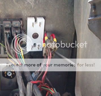
After doing a continuity test between the ignition switch harness disconnect the fuse box (key controlled side), I determined that the Red run wire is isolated from the Blue accessories wire when the switch is in the Start position. It's all handled internally in the switch. So, no back feeding problem. Which means I was also wrong about backfeed prevention being one of the functions of the ballast resistor.
Also, the relays in my drawings are shown having the 85 pin being powered and the 86 pin being grounded. This is incorrect. While this wouldn't matter for the relays I'm using, it would be if they had an internal diode.

Thread
Thread Starter
Forum
Replies
Last Post


