
For you Fury Temp/Fuel/Amp Guage Experts

Thread Starter
Mopar Fan
Joined: Jan 2014
Posts: 65
Likes: 1
From: Pembroke, ON
For you Fury Temp/Fuel/Amp Guage Experts
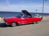
I have a 66 Dodge Monaco convertible (Canadian Model) Which means it has the Plymouth Fury interior. This includes the gauge cluster on the left of the steering wheel for temp/fuel/amps see attached pic. So basically I need 2 shop manuals to cover both the Monaco and Fury.
These are the gauges im having trouble with. The question I have is regarding this so called "Voltage Limiter" that it mentions in the plymouth shop manual.
The problem is when I turn on the ignition, both the fuel and temp gauge will go to high. Under Service diagnosis in the 66 plymouth manual it says it's either (a) faulty voltage limiter or (b) cluster not properly grounded to panel.
Does the Fury gauges have a voltage limiter? If yes...Is this "voltage limiter" internal to the guage cluster because it is not shown on the wiring diagram for the 66 Fury. However it is shown on the wiring diagram for a 66 dodge monaco (Us version).
If it matters, The Shop manual I have for the fury covers 66 Plymouth models such as the Fury I, II & III, Barracuda, Valiant, Belvedere I, II, Satellite, Signet and sport Fury.
Thanks
Glen
Last edited by labradorian70; Dec 31, 2014 at 08:57 PM.

Mopar Lover
Joined: May 2011
Posts: 2,732
Likes: 361
From: Ontario Canada
Thread Starter
Mopar Fan
Joined: Jan 2014
Posts: 65
Likes: 1
From: Pembroke, ON
The wiring diagram for a Fury does not show a voltage limiter in it's wiring diagram, but If I look at a wiring diagram for a Valiant, Belvedere, satelite or Baracuda i see a voltage limiter. The fact that I don't see one on the fury wiring diagram tells me either, 1)there isn't one and the guages work on 12V vs 5V, or 2)the voltage limiter is inside the guage cluster.
I just don't want to start trouble shooting thinking there is a limiter when in fact there isn't. I guess I could just measure the voltage at the guages, but that doesn't really tell me if there is a limiter or not. A failed limiter could have an output of 12V instead of 5.
The fact that I have a monaco with a fury interior has me looking at 2 manuals at once, and adds to the confusion.
I recently got this car from my father, the original owner and the fuel gauge would only go as hi as about 1/4 tank and the temp gauge was intermittent. I decided to replace the temp sensor. but now both gauges go to full when ignition is turned on.
like I said all the literature I have referenced mentions a voltage limiter but i don't see one in the car and the fury wiring diagram does not show one.
cheers, thanks and All the best in 2015.
Glen

Mopar Lover
Joined: Nov 2012
Posts: 1,846
Likes: 140
that wiring shown by allpar will work. but if you check out LM7805 on the internet you can find some variations. some give better voltage spike protection and so on. all so i have seen articals that puts the LM7805 in side the stock housing. and there might be an aftermarket one, if my brain is working right. just search LM7805, or LM317 on the internet, you will find more info than you need. up date: found more info. http://www.chargersourceguide.com/voltagelimiter.html
http://www.rockauto.com/catalog/x,ca...,parttype,4885
https://www.jimsautoparts.com/electric.htm
http://www.rockauto.com/catalog/x,ca...,parttype,4885
https://www.jimsautoparts.com/electric.htm
Last edited by moe7404; Jan 1, 2015 at 11:52 AM.
Thread Starter
Mopar Fan
Joined: Jan 2014
Posts: 65
Likes: 1
From: Pembroke, ON
that wiring shown by allpar will work. but if you check out LM7805 on the internet you can find some variations. some give better voltage spike protection and so on. all so i have seen articals that puts the LM7805 in side the stock housing. and there might be an aftermarket one, if my brain is working right. just search LM7805, or LM317 on the internet, you will find more info than you need.
thanks......Im not trying to find one for my car, at least not yet anyways. I was trying to find where it is located on my car.
In another forum someone mentioned that the voltage limiter on this gauge cluster is located inside the fuel gauge and their is a jumper on the circuit board that in turn feeds the temp gauge. now at least I can test to see if the limiter is working by testing the voltage on the jumper to the temp gauge.
thanks for the info.
cheers
glen
Mopar Lover
Joined: May 2011
Posts: 2,732
Likes: 361
From: Ontario Canada
This is weird, I thought they all had them from '63/'64 but looking at these circuit boards, it's like your car pre '67 don't even have the three slots to solder in a limiter.
Wish I knew more about the '66. I found some stuff in the C Body forums mostly about not working with no mention of voltages or limiters.
My curiosity is spiked.
http://premiumdashdecals.com/dash_ci...ards.htm#cbody
Dan.
Wish I knew more about the '66. I found some stuff in the C Body forums mostly about not working with no mention of voltages or limiters.
My curiosity is spiked.
http://premiumdashdecals.com/dash_ci...ards.htm#cbody
Dan.
Mopar Lover
Joined: Nov 2012
Posts: 1,846
Likes: 140
when other people talk about where the regulator or other things are, i have to say theres a LOT i dont know about Chryslers. so if you say it is this or that i know i will be learning a lot. at the mopar club iam in we have a saying " about Chryslers NEVER SAY NEVER" i did remember this. i have seen mech run bare wire around the two postes on the AMP meter to by pass it and install a volt meter. think about this the AMP meter will never show you that the BATT voltage is low.
Thread Starter
Mopar Fan
Joined: Jan 2014
Posts: 65
Likes: 1
From: Pembroke, ON
This is weird, I thought they all had them from '63/'64 but looking at these circuit boards, it's like your car pre '67 don't even have the three slots to solder in a limiter.
Wish I knew more about the '66. I found some stuff in the C Body forums mostly about not working with no mention of voltages or limiters.
My curiosity is spiked.
http://premiumdashdecals.com/dash_ci...ards.htm#cbody
Dan.
Wish I knew more about the '66. I found some stuff in the C Body forums mostly about not working with no mention of voltages or limiters.
My curiosity is spiked.
http://premiumdashdecals.com/dash_ci...ards.htm#cbody
Dan.
Thanks Dan
Another good link. Just to confirm....it's the part # 2496468 in the link above....that is the circuit board from my gauge cluster. 65-66 fury.
Last edited by labradorian70; Jan 1, 2015 at 03:41 PM.
Thread Starter
Mopar Fan
Joined: Jan 2014
Posts: 65
Likes: 1
From: Pembroke, ON
While Im on this topic.....please see attached pic i found online of the back of another gauge cluster, please note the white arrow down in bottom right side of the pic.
what is this little tube? My gauge cluster does not have this and I know my cluster is original and has never been tampered with.
however I have 2 spare gauge clusters that my father picked years ago and I noticed that one cluster has this little tube and the other does not.
thanks for the help so far guys........greatly appreciated.
Glen
Thread Starter
Mopar Fan
Joined: Jan 2014
Posts: 65
Likes: 1
From: Pembroke, ON
when other people talk about where the regulator or other things are, i have to say theres a LOT i dont know about Chryslers. so if you say it is this or that i know i will be learning a lot. at the mopar club iam in we have a saying " about Chryslers NEVER SAY NEVER" i did remember this. i have seen mech run bare wire around the two postes on the AMP meter to by pass it and install a volt meter. think about this the AMP meter will never show you that the BATT voltage is low.
..Always something to learn.
Thread Starter
Mopar Fan
Joined: Jan 2014
Posts: 65
Likes: 1
From: Pembroke, ON
This is weird, I thought they all had them from '63/'64 but looking at these circuit boards, it's like your car pre '67 don't even have the three slots to solder in a limiter.
Wish I knew more about the '66. I found some stuff in the C Body forums mostly about not working with no mention of voltages or limiters.
My curiosity is spiked.
http://premiumdashdecals.com/dash_ci...ards.htm#cbody
Dan.
Wish I knew more about the '66. I found some stuff in the C Body forums mostly about not working with no mention of voltages or limiters.
My curiosity is spiked.
http://premiumdashdecals.com/dash_ci...ards.htm#cbody
Dan.
Update. I took the gauge cluster out of the car and bench tested it. Had my RV battery and connected up the new fuel sender on the bench. Checked the voltage to the gauges and got about 6v. so voltage limiter seems ok. Moved the tank float and the fuel gauge responded accordingly. Used the fuel sender on the temp gauge also and works fine.
With gauge cluster still out of the car......I sat in the car and measured the resistance to the fuel sender and got about 25ohms. I'm not sure how much fuel is in the tank but it is somewhere between 1/2 and full if my memory serves me right.
Then I measure the temperature sensor resistance from the wiring harness in the dash and also took the temp sensor out and measured it's resistance, and got something like 250ohms?
Knowing the gauge cluster is working i put it back in the car. when I started the car the fuel gauge goes to full. I I brought the car up to temp and waited to see if the temp gauge would rise. it did but went almost to high then would drop off for a bit them go back up again?
When I bench tested temp gauge it was not intermittent, it stayed where it was suppose too.
I even put in a new temp sensor, but with that one the temp gauge went to full and stayed there?
So in summary what should the resistance be of a COLD temp sensor be??? i got over 200ohms, im thinking that is ok, because as the sensor heats up, the resistance should decrease.
Mopar Lover
Joined: May 2011
Posts: 2,732
Likes: 361
From: Ontario Canada
Just now tested one.
Room temp ..................70 F = 262 ohms
Keurig coffee machine 186 F = 28.3 ohms
Has to be ground, strap from block to chassis or battery, wire from sender mount to chassis, circuit board to chassis ????
Room temp ..................70 F = 262 ohms
Keurig coffee machine 186 F = 28.3 ohms
Has to be ground, strap from block to chassis or battery, wire from sender mount to chassis, circuit board to chassis ????
Thread Starter
Mopar Fan
Joined: Jan 2014
Posts: 65
Likes: 1
From: Pembroke, ON
Thanks. 262 sounds about right. the temp in my garage was about 15C(60F) and i was getting about 280 ohms.
Im going to take the temp sensor(Old one) and new one and do what you did, put them in hot water and check ohms.
Is your sender a a TS18? the above test was done with old sensor and like I said got wierd results. with the new sensor(TS18), the gauge just goes to full and stays there.
as for the grounding, i'll try a jumper wire directly from the case of the gauge cluster to the engine chasis, etc. got a gremlin i think.
ground cable from battery to engine block is new.
thanks Dan
Last edited by labradorian70; Jan 2, 2015 at 08:27 PM.
Thread Starter
Mopar Fan
Joined: Jan 2014
Posts: 65
Likes: 1
From: Pembroke, ON
Regarding chassis ground... The battery negative is connected to the engine block. where is the block to chassis ground strap located usually?
thanks
Glen
Thread Starter
Mopar Fan
Joined: Jan 2014
Posts: 65
Likes: 1
From: Pembroke, ON

Mopar Fanatic
Joined: Aug 2014
Posts: 154
Likes: 22
From: London
I have a 65 Fury that I am currently refitting with Auto Meter's American
Muscle gauges and I can say with certainty that there is no voltage
regulator on my car either. One problem I did notice in the past is that
the plug that goes in the back of the triple cluster either falls off or it
makes very bad contact. Good grounds everywhere is the secret with
these older vehicles but don't discount a bad fuel sender or poor/burnt
connections at the bulkhead connector. The fact that the fuel gauge
goes max is a pretty good indication of bad ground or bad connection.
Thread Starter
Mopar Fan
Joined: Jan 2014
Posts: 65
Likes: 1
From: Pembroke, ON
I have a 65 Fury that I am currently refitting with Auto Meter's American
Muscle gauges and I can say with certainty that there is no voltage
regulator on my car either. One problem I did notice in the past is that
the plug that goes in the back of the triple cluster either falls off or it
makes very bad contact. Good grounds everywhere is the secret with
these older vehicles but don't discount a bad fuel sender or poor/burnt
connections at the bulkhead connector. The fact that the fuel gauge
goes max is a pretty good indication of bad ground or bad connection.
Muscle gauges and I can say with certainty that there is no voltage
regulator on my car either. One problem I did notice in the past is that
the plug that goes in the back of the triple cluster either falls off or it
makes very bad contact. Good grounds everywhere is the secret with
these older vehicles but don't discount a bad fuel sender or poor/burnt
connections at the bulkhead connector. The fact that the fuel gauge
goes max is a pretty good indication of bad ground or bad connection.
When I find more time to get back at this, I will try grounding the gauge directly to the engine block(for the temp sensor) and perhaps another ground from engine block to tank(thinking out loud here).
I checked the continuity of the wire from temp sender to firewall and to the gauge plug, good, and measured the resistance to the tank sender, 25ohms.
When I bench tested the gauges, i tried removing the sender ground connection and the gauges went to zero. Im thinking the only reason the gauges would go to full while in the vehicle is sender circuits are shorted(bad senders?) low resistance. As the eng temp rises the resistance decreases.
keep ya posted what i find.
cheers
Last edited by labradorian70; Jan 8, 2015 at 02:03 PM.
Mopar Fanatic
Joined: Aug 2014
Posts: 154
Likes: 22
From: London
If memory serves me, I had basically the same problem and ended up
running a ground wire to the fuel sending unit back to the body and a
ground wire from the engine to the firewall. Just to be on the safe side,
I also ran a set of grounds from the back of the gauge housings to the
dash frame. You had it working when "mocked" up so you should be able
to duplicate that on board the car. You could try wiring the temp
sending unit separately and heating it with a Bic to see if it functions.
I remember the day I found out my horns didn't work because I didn't
have a ground wire bridging the rag joint on my steering column. Who
would have thought when there was none to begin with. Don't discount
the fact that the wire from the fuel sending unit may actually be leaking
to ground as it passes through the car - insulation break down from
40 years of exisitence.
Thread Starter
Mopar Fan
Joined: Jan 2014
Posts: 65
Likes: 1
From: Pembroke, ON
If memory serves me, I had basically the same problem and ended up
running a ground wire to the fuel sending unit back to the body and a
ground wire from the engine to the firewall. Just to be on the safe side,
I also ran a set of grounds from the back of the gauge housings to the
dash frame. You had it working when "mocked" up so you should be able
to duplicate that on board the car. You could try wiring the temp
sending unit separately and heating it with a Bic to see if it functions.
I remember the day I found out my horns didn't work because I didn't
have a ground wire bridging the rag joint on my steering column. Who
would have thought when there was none to begin with. Don't discount
the fact that the wire from the fuel sending unit may actually be leaking
to ground as it passes through the car - insulation break down from
40 years of existence.
Last night i had moment and found the ground between the engine block and firewall and "It sure looks 49 years old" It's looks like a #8 wire from the firewall to just behind #8 cylinder.
Someone mentioned something about a braided strap? but i found this wire. Should this be a wire or strap? what gauge size should it be. I work as a electrical designer and with most electrical grounds we use a #6awg. I guess the bigger the better.
Thanks for the advice, im going to go at this this weekend.
cheers
Last edited by labradorian70; Jan 9, 2015 at 04:47 PM.
Mopar Fanatic
Joined: Aug 2014
Posts: 154
Likes: 22
From: London
I used a small braided strap ( about 1/4 x 7" ) from the engine to the firewall . It was a bit filthy when I found it but a short dip in a
weak solution of Muriatic acid and water brought it back to new condition. Use toothed "shake-proof" washers where ever possible beneath eyelets to ensure good contact. I would check and clean all connectors involved in both the fuel and temp circuits using 400 wet/dry sand paper soaked with WD40 and apply dielectric grease before connecting them. You can temporarily run new wires from the senders to their respective gauges to eliminate existing wire faults.
weak solution of Muriatic acid and water brought it back to new condition. Use toothed "shake-proof" washers where ever possible beneath eyelets to ensure good contact. I would check and clean all connectors involved in both the fuel and temp circuits using 400 wet/dry sand paper soaked with WD40 and apply dielectric grease before connecting them. You can temporarily run new wires from the senders to their respective gauges to eliminate existing wire faults.
Thread Starter
Mopar Fan
Joined: Jan 2014
Posts: 65
Likes: 1
From: Pembroke, ON
I used a small braided strap ( about 1/4 x 7" ) from the engine to the firewall . It was a bit filthy when I found it but a short dip in a
weak solution of Muriatic acid and water brought it back to new condition. Use toothed "shake-proof" washers where ever possible beneath eyelets to ensure good contact. I would check and clean all connectors involved in both the fuel and temp circuits using 400 wet/dry sand paper soaked with WD40 and apply dielectric grease before connecting them. You can temporarily run new wires from the senders to their respective gauges to eliminate existing wire faults.
weak solution of Muriatic acid and water brought it back to new condition. Use toothed "shake-proof" washers where ever possible beneath eyelets to ensure good contact. I would check and clean all connectors involved in both the fuel and temp circuits using 400 wet/dry sand paper soaked with WD40 and apply dielectric grease before connecting them. You can temporarily run new wires from the senders to their respective gauges to eliminate existing wire faults.
UPDATE
I replaced the ground wire with a braided strap between the block and firewall just for piece of mind.
regarding the intermittent temp gauge..... on the rear of the gauge cluster, there are 4 pins where the wire harness plugs on to. the pin for the temp sender was loose I assume that was the intermittent problem.
I had a couple of spare gauge clusters and and I simply took the circuit board off one of the spares and replaced it on the one in the car. temp gauge seems fine now. gas gauge goes to full
Need to crawl under the car and look at sender.
Keep ya posted.
Mopar Fanatic
Joined: Aug 2014
Posts: 154
Likes: 22
From: London
I've posted in the electrical section of the forum on a conversion I am
doing with Autometer's gauges to remedy the exact problem that both
of us have. Take a boo at my post "old to new or old looking".
doing with Autometer's gauges to remedy the exact problem that both
of us have. Take a boo at my post "old to new or old looking".
Thread Starter
Mopar Fan
Joined: Jan 2014
Posts: 65
Likes: 1
From: Pembroke, ON
Your conversion looks great. I will keep this mind if I ever decide to do it.
But for now I plan on keeping the car all stock as it has been since new. My father is the original owner and has passed it on to me. He is still alive and well, wouldn't want him to see me doing such a mod,
 .
. I do like it though. Great job.

New Member
Joined: Oct 2018
Posts: 2
Likes: 2
Instrument Cluser Voltage Regulator
Years ago in the 6 Volt system era, the gauges pretty much operated the same. They were Bi-Metal deflecting gauges which incorporated a Heating Wire wrapped around a Bi-Metal Strip. When heated (VIA the Wire), one of the 2 "Bi-Metals" to expand quicker than the other causing the Bi-Metal strip to distort (Bend). This is the same concept for Coiled Bi-metal units used in Carburetor Choke Coils.
Later General Motors developed a Dual Magnetic Field Gauge.whereas the opposing Magnetic Fields reacting on the Needle would create the Needle fluctuations. G.M. had a Patent on the "Magnetic Field" style that Ford and Chrysler couldn't use. When the Automotive System progressed to 12 Volt Systems, the Higher Voltage wouldn't work on the 6 Volt Gauges. Instead of totally redesigning the Gauges to handle 12 Volts, they elected to "Pulse" the 12 volt power effectively reducing the "Overall" Voltage to an average of 6 Volts.
The ICVR's "Pulse" the power much like a Turn Signal Flasher does, but also use a heating wire around the Arm made of Bi-metal Material. As the Power is being sent to the Gauges, the Wire Heats the Bi-Metal Arm with eventually "Opening" the contacts which halts the Power to the Gauges. Once the circuit is "Open" , the Wire has no current flow and the Bi-metal Arm cools to return back in making contact again... Process repeats. You may notice these gauges will nearly "Full-Swing" when the Ignition is first turned "On", but shortly afterwards start to show proper readings. this is due to the ICVR's Bi-metal Arm warming up. The Term ICVR is ambiguous as the Voltage IS NOT Constant.
New Member
Joined: Oct 2018
Posts: 2
Likes: 2
ICVR, Gauges and Sending Units
ICVR "Pulses" 12 Volt power to the Gauge Bi-Metal Strips Heating Wire that travels to the Sending Unit which in turn varies the percent of "Ground". The "Varied Ground" controls the Current on the Heating Wire wrapped around the Gauges' Bi-Metal Strip (More Current, More "Bending" and more Needle deflection). The Higher Current is through Lower Sender Resistance generally causing the gauge to register on the upper end of its' Scale. The OEM Sending Units are calibrated to compensate for the Gauge Bi-Metal Strip Heating and Cooling rates. Using the Fuel Sending Unit as an example, If the Coiled Resistor Board were flattened out and an Ohmmeter had 1 lead attached to one end of the Resister Coil, as you touch the other lead of the Ohm Meter in 1/8 " increments to the Resistor starting at the end closest to the other Ohmmeter Lead and move to the farthermost end, you will find the Ohm Resistance will not be in secession (5, 10, 15... Ohms). Overall Resistance for an OEM Fuel Sending gauge should be 73.4 Ohms (+/- 3 to 5%) 1/2 way the Resistance Coil should be app 22 to 23 Ohms not 36 to 37 Ohms.(1/2 of 73).
Aftermarket (None OEM) Sending Units are subject to being "Within the Ball Park" to being "Way out in Left Field" (Sorry for the analogies). Test your Senders to their accuracy (App 73 Ohms is Low to "0", app 23 Ohms is 1/2 way, and app 10 Ohms is High to "MAX")
Aftermarket (None OEM) Sending Units are subject to being "Within the Ball Park" to being "Way out in Left Field" (Sorry for the analogies). Test your Senders to their accuracy (App 73 Ohms is Low to "0", app 23 Ohms is 1/2 way, and app 10 Ohms is High to "MAX")

New Member
Joined: Mar 2020
Posts: 1
Likes: 0
I have a 66 Dodge Monaco convertible (Canadian Model) Which means it has the Plymouth Fury interior. This includes the gauge cluster on the left of the steering wheel for temp/fuel/amps see attached pic. So basically I need 2 shop manuals to cover both the Monaco and Fury.
These are the gauges im having trouble with. The question I have is regarding this so called "Voltage Limiter" that it mentions in the plymouth shop manual.
The problem is when I turn on the ignition, both the fuel and temp gauge will go to high. Under Service diagnosis in the 66 plymouth manual it says it's either (a) faulty voltage limiter or (b) cluster not properly grounded to panel.
Does the Fury gauges have a voltage limiter? If yes...Is this "voltage limiter" internal to the guage cluster because it is not shown on the wiring diagram for the 66 Fury. However it is shown on the wiring diagram for a 66 dodge monaco (Us version).
If it matters, The Shop manual I have for the fury covers 66 Plymouth models such as the Fury I, II & III, Barracuda, Valiant, Belvedere I, II, Satellite, Signet and sport Fury.
Thanks
Glen
These are the gauges im having trouble with. The question I have is regarding this so called "Voltage Limiter" that it mentions in the plymouth shop manual.
The problem is when I turn on the ignition, both the fuel and temp gauge will go to high. Under Service diagnosis in the 66 plymouth manual it says it's either (a) faulty voltage limiter or (b) cluster not properly grounded to panel.
Does the Fury gauges have a voltage limiter? If yes...Is this "voltage limiter" internal to the guage cluster because it is not shown on the wiring diagram for the 66 Fury. However it is shown on the wiring diagram for a 66 dodge monaco (Us version).
If it matters, The Shop manual I have for the fury covers 66 Plymouth models such as the Fury I, II & III, Barracuda, Valiant, Belvedere I, II, Satellite, Signet and sport Fury.
Thanks
Glen

Thread
Thread Starter
Forum
Replies
Last Post
labradorian70
Interior/Exterior Electrical
11
Oct 21, 2015 07:04 PM
labradorian70
Interior/Exterior Electrical
1
Mar 29, 2015 05:41 AM


