Electrical gremlin
#32
1 I doubt very much your stock alternator is a 60 A, more likely around 40 No, your stock wiring will NOT support a 100A alternator, read this excellent article from the MAD Electrical site. This article applies to ALL vintage Mopar cars and trucks with a "full current" type ammeter:
came from here:
http://www.madelectrical.com/electri...p-gauges.shtml
http://www.madelectrical.com/electrical-tech.shtml
IN particular, the connections in the bulkhead connector were NEVER meant for the kind of charging current that they must endure. Even "back then" my 70 RR sixpack car developed trouble, and long before "Al Gore" invented the internet, I ran new wire straight through the connector to replace the charging line. I've worked on several Dodge pickups (typically with snowplows) with melted ammeters
I would run whatever resistor Accel tells you.
#33
440 -
Thanks again. As far as the alternator, I think my best bet is to just have the current one rebuilt and save on the headaches. We have a local shop with a pretty good rep.
Currently, the ammeter is bypassed, but it seems that was never the problem. So, in all honestly, I'll probably reconnect it and see what happens. Frankly the only issues I've ever heard about that has been on the Internet. (Sorry, I'm a little skeptical.) If things go south, bypassing it takes about 5 minutes.
As far as Accel, what they are implying is that the stock resistor (approx 5 ohms on the lower and 1 1/4 ohms on the upper) can be replaced by a single 1 1/4 ohm resistor??? That's seems like a bit of a push. Again, I've been given bad info by factory reps before, heck the guy I spoke to could have been a chevy guy.... (Their instructions are adamant about using THEIR resistor, but say nothing about loosing the Mopar factory stuff.)
Not doubting you, just trying to get my arms around this.
Archer
Last edited by Archer; 03-25-2012 at 01:23 PM.
#34
Guys -
Quick update. Brought the alternator in and the guy takes one look at it and said, oh, "you're missing a diode". D'oh.
440 -
All of the research I've done showed that the std alt was 41 amps, heavy duty was 50 and "special package" was 60. Most everyone I've spoken to said that 60 - 65 amps was pretty much the norm and all the replacements I've seen begin at 60 amps.
Archer
#35
Guys -
The alternator is in and all seems well following a very brief test. A longer test will follow, as weather permits.
Here's the problem I'm having intellectually. Yes, there was a diode missing, and yes, it now seems to work, BUT -
The alternator was fully charging the battery and under the load that caused the apparent misfire, the voltage drop was in the 0.1V range. That's within spec and shouldn't have caused anything, but clearly it did.
Any possible explanations why this happened.
Thanks,
Archer
#36
............. there was a diode missing,...................
The alternator was fully charging the battery and under the load that caused the apparent misfire, the voltage drop was in the 0.1V range. That's within spec and shouldn't have caused anything, but clearly it did.
The alternator was fully charging the battery and under the load that caused the apparent misfire, the voltage drop was in the 0.1V range. That's within spec and shouldn't have caused anything, but clearly it did.
But a missing diode (missing, open, shorted) WILL case a huge funny looking output wave that becomes VERY difficult to filter, and WILL make noise in your radio. Additionally, this ripple can affect electronic devices in the car
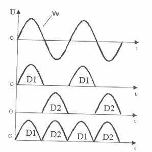
The waveform below is SINGLE phase, like your normal home power, used for illustration.
The top waveform is normal SINGLE phase power going into a rectifier system.
The second and third waveforms are for a 1/2 wave rectifier, in this case they are getting ready to illustrate something following. IF you have an inexpensive charger, like for an electric drill, it MIGHT have a 1/2 wave rectifier, and notice that it produces PULSES of "positive" voltage (in this case) with a big huge HOLE in between each pulse. This is one of the worst types of power supplies to filter into "pure DC" which is done with capacitors and or inductors. Sometimes the inductor is replaced by a resistor
The BOTTOM wave shows the combined output of BOTH 1/2 wave rectifiers, which is known as FULL WAVE rectification. Notice now, that the pulses are right next to each other, and so become much easier to filter.

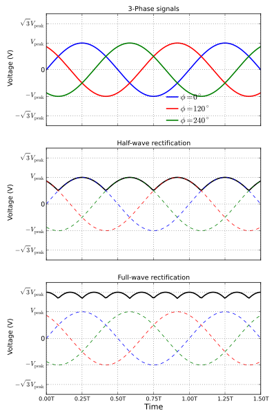
Now a THREE phase wave --like in your alternator--looks something like below. IT is basically THREE SINGLE phase outputs which are PHASED 1/3 of a wave apart
So in the top waveform, we see the three distinct AC waveforms, which are generated --one for each of the 3 stator windings
In the middle drawing, we see a 1/2 wave rectifier,
and in the bottom, a full wave rectifier, the smoothest and easiest to filter there is

Some more reading on the subject:
http://en.wikipedia.org/wiki/Rectifier

Below are a couple of waveforms of alternators with bad diodes. You can just "hear" the buzz it causes in the vehicle system!!!


Last edited by 440roadrunner; 03-31-2012 at 01:37 PM.
The following users liked this post:
Archer (03-31-2012)
#37
440 -
Thank you!
That's what I needed to know. That makes perfect sense.
AND - if the car had a radio (which it doesn't), it might have made the problem a little more obvious - d'oh!
Archer
Thank you!
That's what I needed to know. That makes perfect sense.
AND - if the car had a radio (which it doesn't), it might have made the problem a little more obvious - d'oh!
Archer
Last edited by Archer; 03-31-2012 at 08:21 PM.
Thread
Thread Starter
Forum
Replies
Last Post


