
72 cuda ignition problems


Thread Starter
New Member
Joined: Jul 2014
Posts: 15
Likes: 0
72 cuda ignition problems
hello, Im new to the thread and joined because I love e bodies. I have a 72 barracuda that I have been fighting ignition problems with for over a month. I was driving and had car lose spark. I had the inline fuse at the starter relay blow and melted the ignition switch wiring harness plug at the base of the steering column. So far I have replaced the ignition switch tumbler, ignition switch and harness down column, dual resistor ballast, ignition module, engine wiring harness, coil, starter, starter relay and battery and still wont run. This is what is going on, I have 12 volts at + side of coil in run position but drop to 7 when cranking but if I unplug pentistar plug from ecu the + side of coil reads 12 while cranking. At the blue yellow wire at the ecu plug I have 12 volts in the run position but drop to 8.7 when I crank engine? I unplugged the - side of coil and grounded the terminal and took coil wire off the top of the dist. and placed it next to the intake and in run I have no spark but in crank position or start I have 1 spark and it only seems to spark when I release the key. Only 1 spark when key is released. What is wrong guys, I have never felt so stupid as I have while working on this. Everything is new and nothing is right

Mopar Lover
Joined: Nov 2007
Posts: 2,424
Likes: 248
All these cars pretty much work the same.
First, visit this thread
http://www.forabodiesonly.com/mopar/...p?p=1970088617
and download yourself a free 72 Chrysler service manual
More good info here
http://www.mymopar.com/index.php?pid=31
Now, the starting voltage during crank comes from the ignition switch, usually known as "IGN 2" or the "bypass circuit."
So, from the key, going through the bulkhead, you have TWO power sources, "IGN 1" which is "run" and in start, IGN 2 which supplies the coil + side of the key
It sounds as if the bypass circuit is the problem. This is a SIMPLE deal. It's one wire coming off the IGN switch, goes through the bulkhead, and feeds the coil + side of the ballast resistor
Here's a simplified diagram:

Follow the BLUE wire. It comes off the IGN switch, but the bulkhead connector is not shown. Notice that it branches off and feeds several components. Depending on the year, the car, and options, generally this one feed which is NOT fused feeds
the ignition run power
alternator field
voltage regulator I terminal
electric choke if used
idle solenoid on some cars, and retard solenoid some cars
smog doo dads on some vehicles
One drawn a bit different:
http://www.mymopar.com/downloads/Dual_Ballast_5pin.pdf
Now, the reason you are reading 12V when you unplugged the ECU is that you have removed the LOAD on the circuit. There is something "in there" either a bad connection in the bulkhead, or a splice, or at the IGN switch connector or right in the switch, that is causing VOLTAGE DROP under load
============================================
BYPASS circuit. This is the DOTTED BROWN coming off IGN2 at the key. It goes to the "coil +" side of the ballast resistor. When you twist the key, this is powered, and is supposed to feed battery direct to the coil. It powers the ECU by BACKFEEDING through the ballast resistor
To try and simplify this rambling, you should normally have "same as battery" voltage:
1......In run, everything hooked normal, engine off. Hook one probe to the "high" side of the ballast or the blue alternator field connection. Hook your other probe to battery POSITIVE post. With the key in "run" you should have VERY little voltage reading, the less the better. More than .3V (three tenths of one volt) means you have a bad connection in that path
GENERALLY the path is battery positive.....fuse link......bulkhead connector......ammeter......in harness splice........ignition switch connector.......through the switch........back out the switch connector.......back through the bulkhead connector..........to the underhood loads
2.......CRANK. This is sort of the same deal, except now power is being supplied by the IGN2 wire. Hook one probe to coil+, the other to battery +. Take reading while cranking WITH THE KEY. Once again, the lower the reading the better, and over .3V means trouble.
Now PART of this you already know. The trick is FINDING it
1.........Look in the engine bay harness........Do you have a WHITE plastic connector separating part of the engine harness from the rest? Check that first
2........No1 suspect is usually the bulkhead connector
3.........The ignition switch connector at the column is a fair suspect
4.........The switch itself. Just because "it's new" does not mean 'good'
5.........More rare, but possible, is the ammeter connections, the wire ends on those wires, or internal problems in the ammeter
6.........Even more rare BUT HAS HAPPENED is failure of the "in harness splice." This is a factory welded splice in the black ammeter wire up near the cluster. You have to pull the cluster and untape part of the harness, working your way down from the ammeter black wire, to find it. I would save this for LAST
=========================================
How to find? Easy, in theory. Start taking voltage measurements "along the path." Accessing the easy points first allows you to divide the problem. I use the "voltage drop" method, that is, one probe clipped to battery positive.
If it is easier, ground one probe, and constantly subtract readings from the battery to determine if you are getting close
EXAMPLE. You clip the meter to battery positive. You use an extended wire for this, FUSED. So one end of the meter is hooked to battery
You go into the car, you hook the remaining probe to the "run" wire coming out of the switch connector. You probe that on BOTH sides of the connector. The reading changes "let's say" by less than a tenth of a volt. You wiggle the connector. No change.
Hook the probe to the "bypass" circuit. Crank the engine. The reading is too high, maybe 2 volts. You move the probe to the switch side of the connector. It drops way down, maybe .4V THAT CONNECTION is giving you trouble.
Or maybe it doesn't change much. The "key" side of the connection still has a lot of drop. WHERE is this drop coming from? Is it coming from the bulkhead connector? You move the meter probe to the "hot" feeding INTO the switch. THAT reading is OK when cranking.
Conclusion: Voltage drop INTO the switch is OK, but drop is high coming OUT going to the IGN1 "bypass." What's between the two? THE SWITCH. Maybe your brand new switch is AFU.
This is just an example. You have to chase it down this path. Post back, we can step you through this. WRITE DOWN your measurements and HOW you took them.
You MUST take measurements "under a load" IE while cranking for the bypass circuit, and with all accessories hooked up "as normal" that is, until you find something suspicious
First, visit this thread
http://www.forabodiesonly.com/mopar/...p?p=1970088617
and download yourself a free 72 Chrysler service manual
More good info here
http://www.mymopar.com/index.php?pid=31
Now, the starting voltage during crank comes from the ignition switch, usually known as "IGN 2" or the "bypass circuit."
So, from the key, going through the bulkhead, you have TWO power sources, "IGN 1" which is "run" and in start, IGN 2 which supplies the coil + side of the key
It sounds as if the bypass circuit is the problem. This is a SIMPLE deal. It's one wire coming off the IGN switch, goes through the bulkhead, and feeds the coil + side of the ballast resistor
Here's a simplified diagram:
Follow the BLUE wire. It comes off the IGN switch, but the bulkhead connector is not shown. Notice that it branches off and feeds several components. Depending on the year, the car, and options, generally this one feed which is NOT fused feeds
the ignition run power
alternator field
voltage regulator I terminal
electric choke if used
idle solenoid on some cars, and retard solenoid some cars
smog doo dads on some vehicles
One drawn a bit different:
http://www.mymopar.com/downloads/Dual_Ballast_5pin.pdf
Now, the reason you are reading 12V when you unplugged the ECU is that you have removed the LOAD on the circuit. There is something "in there" either a bad connection in the bulkhead, or a splice, or at the IGN switch connector or right in the switch, that is causing VOLTAGE DROP under load
============================================
BYPASS circuit. This is the DOTTED BROWN coming off IGN2 at the key. It goes to the "coil +" side of the ballast resistor. When you twist the key, this is powered, and is supposed to feed battery direct to the coil. It powers the ECU by BACKFEEDING through the ballast resistor
To try and simplify this rambling, you should normally have "same as battery" voltage:
1......In run, everything hooked normal, engine off. Hook one probe to the "high" side of the ballast or the blue alternator field connection. Hook your other probe to battery POSITIVE post. With the key in "run" you should have VERY little voltage reading, the less the better. More than .3V (three tenths of one volt) means you have a bad connection in that path
GENERALLY the path is battery positive.....fuse link......bulkhead connector......ammeter......in harness splice........ignition switch connector.......through the switch........back out the switch connector.......back through the bulkhead connector..........to the underhood loads
2.......CRANK. This is sort of the same deal, except now power is being supplied by the IGN2 wire. Hook one probe to coil+, the other to battery +. Take reading while cranking WITH THE KEY. Once again, the lower the reading the better, and over .3V means trouble.
Now PART of this you already know. The trick is FINDING it
1.........Look in the engine bay harness........Do you have a WHITE plastic connector separating part of the engine harness from the rest? Check that first
2........No1 suspect is usually the bulkhead connector
3.........The ignition switch connector at the column is a fair suspect
4.........The switch itself. Just because "it's new" does not mean 'good'
5.........More rare, but possible, is the ammeter connections, the wire ends on those wires, or internal problems in the ammeter
6.........Even more rare BUT HAS HAPPENED is failure of the "in harness splice." This is a factory welded splice in the black ammeter wire up near the cluster. You have to pull the cluster and untape part of the harness, working your way down from the ammeter black wire, to find it. I would save this for LAST
=========================================
How to find? Easy, in theory. Start taking voltage measurements "along the path." Accessing the easy points first allows you to divide the problem. I use the "voltage drop" method, that is, one probe clipped to battery positive.
If it is easier, ground one probe, and constantly subtract readings from the battery to determine if you are getting close
EXAMPLE. You clip the meter to battery positive. You use an extended wire for this, FUSED. So one end of the meter is hooked to battery
You go into the car, you hook the remaining probe to the "run" wire coming out of the switch connector. You probe that on BOTH sides of the connector. The reading changes "let's say" by less than a tenth of a volt. You wiggle the connector. No change.
Hook the probe to the "bypass" circuit. Crank the engine. The reading is too high, maybe 2 volts. You move the probe to the switch side of the connector. It drops way down, maybe .4V THAT CONNECTION is giving you trouble.
Or maybe it doesn't change much. The "key" side of the connection still has a lot of drop. WHERE is this drop coming from? Is it coming from the bulkhead connector? You move the meter probe to the "hot" feeding INTO the switch. THAT reading is OK when cranking.
Conclusion: Voltage drop INTO the switch is OK, but drop is high coming OUT going to the IGN1 "bypass." What's between the two? THE SWITCH. Maybe your brand new switch is AFU.
This is just an example. You have to chase it down this path. Post back, we can step you through this. WRITE DOWN your measurements and HOW you took them.
You MUST take measurements "under a load" IE while cranking for the bypass circuit, and with all accessories hooked up "as normal" that is, until you find something suspicious
Last edited by 440roadrunner; Jul 17, 2014 at 07:08 AM.

Thread Starter
New Member
Joined: Jul 2014
Posts: 15
Likes: 0
440runner your information is the main reason I joined...have seen your advice on issues for a long time. When the ignition switch at base of column melted I cut it out and when I got new harness with switch I cut switch off of it and did connections matching color to color. On the new switch there were all the same colored wires yellow, blue, black, red and blue but on the new one there was a small 16 gauge black wire that went to switch...my plug didn't show any corresponding wire for this black one so I taped it up not knowing what it was for? The previous owner had the amp meter go out in the dash so instead of replacing original he just took leads and bolted them together and taped up secure. The engine harness is new from Classic Industries...I shouldn't have to open up a new harness should I...and yes there is a white plastic piece in harness..wasn't really for sure what it was for. you say #1 suspect is bulkhead connector...how do I check this..from under dash it looks secure and on firewall I looked in plugholes and they looked fairly grease free...I did spray some brake cleaner into bulkhead to clean out...maybe not a good idea but it did clean things. thanks again for everything will post again tomorrow some results.
Mopar Lover
Joined: Nov 2007
Posts: 2,424
Likes: 248
As I said earlier, "access what you can" first, so a further example
If you access the connections going into the ignition switch and the battery voltage TO the switch seems low "under load"
Then the next likely suspect is the RED battery feed coming in from the bulkhead. About all you can do is to probe it in the engine bay with the key in run, take a reading...........
Then go inside and argue with it to get the 'backside.' I realize this is difficult on some cars.
Another related approach is to monitor input voltage to ign switch with key in 'run' and go out and watch the meter while wiggling the bulkhead connector.
Just because the ammeter was bolted together, do not "assume" The wire ends can be defective (I've found this) and the bolt could have come loose / rusted etc.
You just have to access what you can "in the path" and divide into "sections.
So if it's "bad" at the ignition switch" but "good" at the red (fuse link) going "into" the bulkhead, then the "only things" in that section are
the interior side of the bulkhead
the ammeter bolt
the in harness splice.
The above just an example.
Take some readings and post them. I can step you through. Again, you want "under a load." Try with key "in run" and the heater, radio, etc turned on.
Take some readings say.........
engine side of the bulkhead
interior side if you can get to it
input and 'output' of the ignition switch
If say, the "run" voltage is "good" coming out of the ignition switch on the "dash harness" side of that connector, the only thing between there and the under-hood loads then is the bulkhead connector and any splices in the under-hood harness, and the white engine connector.
Thread Starter
New Member
Joined: Jul 2014
Posts: 15
Likes: 0
ok, I have 12v on the red wire leaving the battery at the bulkhead, I checked for drop under the dash and on the red wire before it got to the plug had a 0.0 loss of volts so i plugged the red wire into the red wire going to ignition switch and had a .3 loss in the run position at the connection. Than checked the blue wire coming from switch and had a .49 loss. So I am losing half a volt between the ignition plug thru the new ignition switch and back down column. You said above that the new switch may be afu...so do i just accept that the .49 loss coming back down the blue wire is to much and start pullin off steering wheel again. can you explain how the juice comes into to the amp meter? does all juice come in thru bulkhead into amp meter then jump down to switch for ignition...if this is how it works then am i to assume that the 0.0 loss I had on red wire before it got the ign. plug (by plug i mean the flat plug with connections going up column) is meaning the amp meter being bypassed is solid? Seems akward, i can overhaul engines and yet I struggle with wiring. Apreciate your help.
Mopar Lover
Joined: Nov 2007
Posts: 2,424
Likes: 248
This article has a great simplified diagram that shows the basic main power of most all these cars
http://www.madelectrical.com/electri...p-gauges.shtml
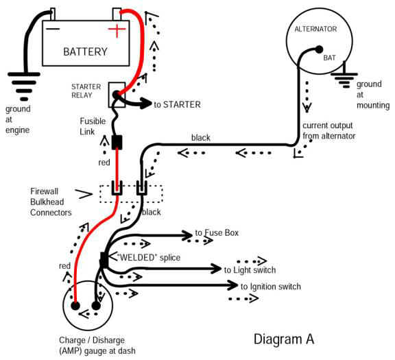
Now, assuming that your ammeter has simply been jumpered across, and no other changes have been made, follow along
Main power for everything except the starter comes off the battery and depending on model, either down to the starter and back up to the relay battery stud, or else from the battery to the relay stud and then down to the battery.
In any case "main battery" starts off pretty much at the starter relay battery stud
Next, main power goes through the main fuse link on the RED, and through the bulkhead to the AMMETER. Through the meter, and then to the BLACK wire and on to the WELDED SPLICE
Power then branches off at the WELDED SPLICE and goes several places depending on year / model
off to the fuse box "hot" buss
off to the headlight switch for headlight ONLY power. Theres a breaker for the headlights in the switch
off to the IGNITION SWITCH
==============================================
Back to your switch. I would double check this. Check the infeed on BOTH sides of the connector going to the switch, and coming out
to IGNITION
and to ACCESSORY
There is an "easy" way to fix this without changing yet another switch, and in some ways this might be BETTER
That is, get under the hood where the IGN RUN feed comes out the bulkhead and cut that. Use the feed coming out into the bay to trigger a good quality relay
Feed power to the relay contacts through a large, say, 30A fuse off the starter relay "stud."
Then take off your underhood loads, IGN, VR, etc, off the output of that relay.
OTHER THAN low voltage to underhood loads with the engine off, 1/2 volt causes ANOTHER problem
With this nearly 1/2 volt drop, your VOLTAGE REGULATOR is supplied this "low" power to the VR IGN terminal. This not only powers the VR, it is the "sensing" terminal. THIS CAUSES the VR to OVERCHARGE the battery. If the VR is correctly working at 13.8--14.2V, it ADDS this 1/2 volt right on top, and now you will charge at 14.2 + .5 (whatever the drop is) for 14.7, nearly 15 volts.
http://www.madelectrical.com/electri...p-gauges.shtml
Now, assuming that your ammeter has simply been jumpered across, and no other changes have been made, follow along
Main power for everything except the starter comes off the battery and depending on model, either down to the starter and back up to the relay battery stud, or else from the battery to the relay stud and then down to the battery.
In any case "main battery" starts off pretty much at the starter relay battery stud
Next, main power goes through the main fuse link on the RED, and through the bulkhead to the AMMETER. Through the meter, and then to the BLACK wire and on to the WELDED SPLICE
Power then branches off at the WELDED SPLICE and goes several places depending on year / model
off to the fuse box "hot" buss
off to the headlight switch for headlight ONLY power. Theres a breaker for the headlights in the switch
off to the IGNITION SWITCH
==============================================
Back to your switch. I would double check this. Check the infeed on BOTH sides of the connector going to the switch, and coming out
to IGNITION
and to ACCESSORY
There is an "easy" way to fix this without changing yet another switch, and in some ways this might be BETTER
That is, get under the hood where the IGN RUN feed comes out the bulkhead and cut that. Use the feed coming out into the bay to trigger a good quality relay
Feed power to the relay contacts through a large, say, 30A fuse off the starter relay "stud."
Then take off your underhood loads, IGN, VR, etc, off the output of that relay.
OTHER THAN low voltage to underhood loads with the engine off, 1/2 volt causes ANOTHER problem
With this nearly 1/2 volt drop, your VOLTAGE REGULATOR is supplied this "low" power to the VR IGN terminal. This not only powers the VR, it is the "sensing" terminal. THIS CAUSES the VR to OVERCHARGE the battery. If the VR is correctly working at 13.8--14.2V, it ADDS this 1/2 volt right on top, and now you will charge at 14.2 + .5 (whatever the drop is) for 14.7, nearly 15 volts.
Last edited by 440roadrunner; Jul 17, 2014 at 06:44 PM.
Mopar Lover
Joined: Nov 2007
Posts: 2,424
Likes: 248
Make CERTAIN that when you measure these drops you "go back" and double check readings. Make certain that you measure with the switch in "run" so that there is a load. If you see "zero" volts drop, it is more likely that you don't have a load on the test circuit than likely you actually don't have any drop LOL
It seems to me you are starting to understand more of this. I think you just need to get your feet wet. Treat this like a road map. Refer to the MAD diagram. It gives you a very good simplified view. You can print it and add to it. Add the switch, the switch connector, the blue going back through the bulkhead, any splices under the hood, and the underhood loads.
You can mark it up with volt readings and in time "see" just what is going on.
Thread Starter
New Member
Joined: Jul 2014
Posts: 15
Likes: 0
"that is, get under the hood where the IGN RUN feed comes out the bulkhead and cut that. Use the feed coming out into the bay to trigger a good quality relay
Feed power to the relay contacts through a large, say, 30A fuse off the starter relay "stud."
Then take off your underhood loads, IGN, VR, etc, off the output of that relay.
OTHER THAN low voltage to underhood loads with the engine off, 1/2 volt causes ANOTHER problem
With this nearly 1/2 volt drop, your VOLTAGE REGULATOR is supplied this "low" power to the VR IGN terminal. This not only powers the VR, it is the "sensing" terminal. THIS CAUSES the VR to OVERCHARGE the battery. If the VR is correctly working at 13.8--14.2V, it ADDS this 1/2 volt right on top, and now you will charge at 14.2 + .5 (whatever the drop is) for 14.7, nearly 15 volts."
I think Im following you...but talk about cutting a new wiring harness all to hell...cutting out the black wire to the alternator would fubar the new harness wrap....will have to think about that one..
never really got to why im firing when I stop craking....let me think for a while on the mad diagram....if we do this we are essentially re routing wires instead of thru the bulk head with spades we are just bypassing the bulkhead? still going thru the red and black wires ...just feeding battery off of starter relay via the alternator...how does the ign 2 wire get its feed to give extra fire to start...off of the black where it branches out?? still trying to figure out how this will help me get fire on ign 2...seems like all its doing is getting all the juice away from spades in bulkhead?? will try tomorrow night....thanks
So I still have the issue of it trying to fire when I let off of the cranking...no spark when in run or reduced spark at least...Im really swimming and not doing very good at it...I will
Thread Starter
New Member
Joined: Jul 2014
Posts: 15
Likes: 0
ok, morning has come and thinking clearer. looking again at the mad diagram, what we are trying to do is get away from the spades at the bulkhead? Am I seeing correctly, this is the only advantage to this setup? Im fine with trying this, just not for sure how this will make me not have to replace my switch, in your post above you mention this may be a better way to do wiring and it maybe not replace switch. So if I checked the red wire at bulkhead and coming out under dash and have no loss or very little, but then when I plug into ign. switch plug and have a loss of .3 is this exceptable? Does this mean my switch is pulling to much draw?
I checked the blue wire coming back down from the ign. switch which supplies power to resistor, vr, and goes to a field on alt if im correct?
Should I have checked the black wire coming back down from the switch, wouldn't this have a lower reading then battery since the power has went thru the switch and spliced off to other acc?
I am confused, the red comes in to amp meter, splices off going to acc and others including supplying power to switch which in turn as the switch is turned to start it sends juice down the ign. 1 wire and then when the switch is turned further to crank it sends juice down the ign. 2 brown wire..to ballast and to coil +...
If this is correct to me it seems like my switch isn't sending juice when it needs to?? How will rerouting my red and black like the mad diagram fix this?
thanks your patience.
Mopar Lover
Joined: Nov 2007
Posts: 2,424
Likes: 248
OK, I'm not necessarily suggesting you do the MAD modification---at least until you find what the trouble is. The point at this particular time is that simplified diagram (I posted) which shows how the current goes through the system
Try to treat this as a road map, maybe a road map as you "drive along" and watch the "gas gauge" of your voltmeter drop. At each connection..........as the voltage "drives along" through the bulkhead, through the ignition switch, you lose a little bit here and there
.3 at whatever point is getting to be close to what I'd accept.
To repeat, you would NOT necessarily need to replace the switch if it is the problem. If it "works" but simply has a lot of drop, you could RELIEVE the load on the switch by cutting loose all loads from your blue ignition wire
Use the key (blue wire) to trigger a good relay, and pull your ignition loads off that relay. This is just an example of "one way."
Remember that CURRENT is what is causing the voltage drop to show up.
POOR CONNECTIONS is the root cause of the drop

Thread Starter
New Member
Joined: Jul 2014
Posts: 15
Likes: 0
Over the weekend I will trace the red wire thru the fuse box checking the volts again. Im planning on pulling out the dash also to check and crimp and solder (sp) the connection at the amp gauge...who knows, maybe its cooked. While im there I will check here and there to make sure I have 12v or close to. Then I will use your road map and check voltage here and there on the black going to switch and out to alt. then the yellow coming from the switch to the starter relay looking for 12, then the brown in the run position looking for 12 under dash from switch and then at resistor and + coil lastly the blue...this will be under dash and then at places it stops...Im guessing all should have 12 or really close..I will write all voltages and locations down and check back with you on sunday or Monday...one thing can you tell me what wires should have power in what key locations again...I have seen your posts in the pasts describing colors and power in this and that just so I know for sure where key needs to be when I test with tester light. thanks again for everything....and bob I thought about that ECU being bad also, I took the new one which is 4 pin off the car and put my old 5 pin back on and that's when I started getting 1 spark when I turned the key back out of crank. don't know what to do with that now?

Mopar Lover
Joined: Nov 2007
Posts: 2,424
Likes: 248
Another thing (I think I forgot LOL) to try is simply hook a clip lead right to coil+ and the battery, then crank the engine and see if you have spark.
This of course will bypass all the wiring troubles except for the short harness between the box, ballast, and distributor.
This of course will bypass all the wiring troubles except for the short harness between the box, ballast, and distributor.
Thread Starter
New Member
Joined: Jul 2014
Posts: 15
Likes: 0
ok, things I know....I have loose or corroded or burnt bulkhead and most likely a bad ign. switch. I tested volts on the brown wire at the bottom of the column when cranking and had 9.8 volts...tested brown under hood on brown wire and had 9.8...leads me to believe switch is bad.
I pulled dash and soldered the red and black wires at the back of amp gauge. tested volts there and had 12.6 same as battery so I know I have power to switch,
tested black wire under hood at bulk head and had 12.6 plugged in harness and tested back of new harness plug and had 11.6 so I have a bad or loose connection between new plug male and bulk head female..will probably run black wire directly beside bulkhead like mad diagram for black wire. I dont want to go thru bulkhead but will drill small hole and put in grommet to protect and then route black.
yellow wire is good on volts at starter relay
Blue wire is another one...I have 12.6 under hood at bulkhead female then when I plug in new harness to bulkhead I have 11.6 at back of new plug...leading me to think same as black wire...new male spade in plug isnt making good contact in bulkhead...holes in bulkhead or opened up and most likely no making contact with new plug males....my plan....
1. I dont want to even think about replacing new bulkhead and all new wires to everything...700$ for harness and new wires....
2. I should be able to splice into blue under dash on wire from ignition switch, not cut it but splice into it and run separate wire thru hole in firewall with grommet to protect wire and then pull blue wire out of new harness plug under hood and make connection...I will still have power to bulkhead on main blue for things it powers under dash (cluster) and the splice will run power to soldered union I will make beside bulkhead...kinda like the mad diagram but instead of drilling bulkhead I will make small hole in firewall and put a grommet in it.
the brown wire only having 9.8 when cranking coming from switch leads me to believe I will not be buying a new switch from autozone againg but thru a dodge dealership if possible and replacing my new switch again...is what you are thinking would cause my low volts on the brown...9.8 going out while cranking isnt near enough?? let me know what you think about my numbers and about me splicing into the blue ....thanks alot.
Thread Starter
New Member
Joined: Jul 2014
Posts: 15
Likes: 0
440 I forgot to mention in my last post that I did run a jumper from + side of battery to + side of coil and you can hear the coil wire to dist. firing but car wont start...I pulled the wire out of the dist. top and when the wire touched the battery + the coil lead would arc to the carb. from 1/2" . One other thing that seems funny, yesterday while working on it it seems like I have an ignition key switch that has an extra position...I mean you have the first spot, run then you have a distinctive second spot should be start than it turns farther almost like there is a detent before it cranks before it actually cranks...is this nothing or should I look at it closer when I work on switch?
Thread Starter
New Member
Joined: Jul 2014
Posts: 15
Likes: 0
is the loss of the 1 volt on the blue and black wire and the 9.8 volts going thru the bulk head on the brown enough to make things not start? I don't know what things have to have to fire at plugs? Sounds funny, but does engine need 12 volts to coil from the brown and 12 on the blue? Does the splice on the blue seem logical?
Thread Starter
New Member
Joined: Jul 2014
Posts: 15
Likes: 0
Can someone explain ...i have a 5 pin ecu warness and my old ecu box was a 5 pin...when hou buy new ecu boxes they come as a 4 pin...what wire is going to an empty hole...seems like the 4 pin ecu wouldnt work for a. 5 pin harness but everyone says they do...what wire isnt getting power
Mopar Lover
Joined: Nov 2007
Posts: 2,424
Likes: 248
The 4 pin box is wired to get power off the wire that's already there, going direct to switched 12V. That wire is already present in the old 5 pin harness
In this diagram it's labled "new wire" going to the far upper right corner. This was a diagram illustrating a conversion from points, so that's why it says "new wire."

In your old 5 pin, the entire "other side" of the second ballast (the other half of the 4 pin ballast) is eliminated for the 4 pin box. that connection was redesigned into the internals of the 4 pin box
The short answer is a 4 pin box can use either a 2 or 4 pin ballast
The older 5 pin box MUST have a 4 pin resistor / harness
In this diagram it's labled "new wire" going to the far upper right corner. This was a diagram illustrating a conversion from points, so that's why it says "new wire."
In your old 5 pin, the entire "other side" of the second ballast (the other half of the 4 pin ballast) is eliminated for the 4 pin box. that connection was redesigned into the internals of the 4 pin box
The short answer is a 4 pin box can use either a 2 or 4 pin ballast
The older 5 pin box MUST have a 4 pin resistor / harness
Thread Starter
New Member
Joined: Jul 2014
Posts: 15
Likes: 0
First thing im going to do is run a jumper off the blue ign. 1 wire under dash by splicing into it under dash. this should still provide power to my cluster and then the splice will bypass the bulkhead and provide the full volts to the ballast then to ecu and then to field on alternator (if im following my map correctly). second im gong to reroute the black wire thru the firewall along side the bulkhead bypassing burnt connector in bulkhead thus supplying full volts to alternator. third Im thinking I will run some more volts tests coming out of the ecu to pickup coil and coil. Maybe replace ecu again. Lastly I have to guess why my brown ign. 2 wire just has 9.8v coming from switch...maybe a short in the new switch?? 440 is this your assumption on the brown? Im not for sure what else would make the brown ign. 2 only send 9.8v to the ballast and then onto the coil....im planning on taking the ign. key switch out again...the extra stop for the key is troubling me some..before I replace ign. switch and wiring harness I will replace key switch again and see what ign. 2 is sending out at switch? Anyone have any thoughts on the ign.2??
Thread Starter
New Member
Joined: Jul 2014
Posts: 15
Likes: 0
Question for anyone..behind the dash on a 72 cuda to be more specific behind the right hand side of the cluster there is a pair of wires that go to a black tube which is approx. 1" long...going into and out of the connection is a yellow and yellow with brown trace wire and the same going out..my question is what is this connector? I have looked on wiring diagram and cant really find it...on my car it is burnt in half or broke in half...seems like it might have a thin film of rubber over it...could it be a resistor or some sort?
I did get the car running...found out the NEW ecm was bad...replaced it and the car started and ran for about 30 seconds and as I shut it off it burnt the inline fusible link at the starter relay again. Finally had to call a mechanic in and his belief is the alternator is over charging and has taken the regulator on firewall out which is why I have had to replace 3 ECM units already and the radio quit and why I keep popping fuses at the starter relay. This might be why the connector at the beginning is burnt up also? Going on 3 months now working on ignition gremlins.
I did get the car running...found out the NEW ecm was bad...replaced it and the car started and ran for about 30 seconds and as I shut it off it burnt the inline fusible link at the starter relay again. Finally had to call a mechanic in and his belief is the alternator is over charging and has taken the regulator on firewall out which is why I have had to replace 3 ECM units already and the radio quit and why I keep popping fuses at the starter relay. This might be why the connector at the beginning is burnt up also? Going on 3 months now working on ignition gremlins.

Thread
Thread Starter
Forum
Replies
Last Post
a.johansson84
Interior/Exterior Electrical
7
May 27, 2012 03:30 AM
GMdude
Do-It-yourself Section
5
Jul 9, 2009 04:42 PM
alsparl
Do-It-yourself Section
21
Jul 7, 2009 03:39 AM


